
Valve seat grinding, clamping and moving device

A technology for moving devices and valve seats, which is applied in the direction of grinding drive devices, seat surface grinders, grinding machines, etc. It can solve the problems of reduced processing efficiency, difficulty in adjusting the pressure of the valve seat and the ball core, and adjusting the grinding effect of the valve seat and the ball core, etc. , to achieve the effect of reducing workload and improving processing efficiency

Pending Publication Date: 2021-01-01
CHONGQING CHUANYI CONTROL VALVE
View PDF0 Cites 2 Cited by
  • Summary
  • Abstract
  • Description
  • Claims
  • Application Information

AI Technical Summary

Problems solved by technology

However, the current matching and grinding equipment can only make the relative rotation between the valve seat and the ball core, and it is difficult to adjust the pressure between the valve seat and the ball core during the grinding process, that is, it is difficult to adjust the pressure between the valve seat and the ball core during the grinding process. The grinding effect needs to be suspended during adjustment, resulting in a decrease in processing efficiency

Method used


Image

  • Valve seat grinding, clamping and moving device
  • Valve seat grinding, clamping and moving device
  • Valve seat grinding, clamping and moving device

Examples


Embodiment 1

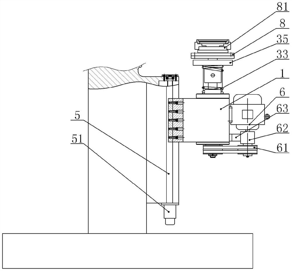
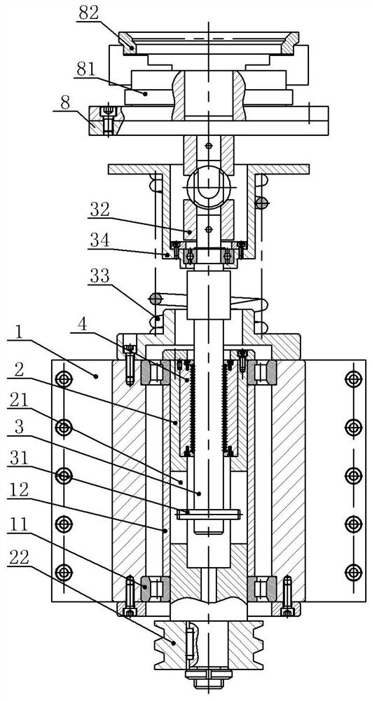
[0039] Seat lapping clamping mobile device, such as figure 1 , figure 2As shown, it includes the bed, the valve seat clamping mechanism and the valve seat clamping movement mechanism. The valve seat clamping mechanism includes the transmission spindle 2, the transmission shaft 3, the clamping mechanism base 1 and the spring 33, the transmission shaft 3 and the transmission spindle 2 are arranged vertically, the transmission spindle 2 vertically runs through the clamping mechanism base 1 and is coaxial with the clamping mechanism base 1, and a bearing positioning sleeve 12 and two Rolling bearings, the two rolling bearings are located at both ends of the bearing positioning sleeve 12, specifically, the rolling bearings in this embodiment use cylindrical roller bearings 11, the bearing positioning sleeve 12 uses cylindrical roller bearing positioning sleeves, cylindrical roller bearings and cylindrical roller bearings The installation methods of the sub-positioning sleeves are...

Embodiment 2

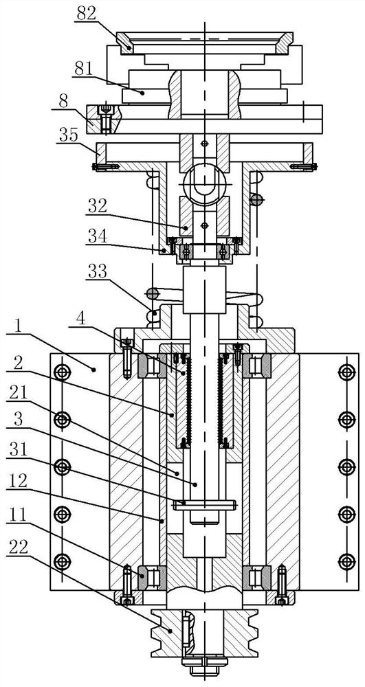
[0054] On the basis of Example 1, such as image 3 As shown, a stopper 35 is provided below the self-centering chuck 81 in this embodiment. The stopper 35 in this embodiment is an annular stop ring, and the inner wall of the stop ring is in contact with the upper end of the spring seat 34. Paste and fix with the spring seat 34 by bolts, so that the limit ring can rotate with the transmission shaft 3.

[0055] During the use of the device in this embodiment, when the chuck seat 8 tilts under the valve seat 82 or its own gravity, it can be blocked by the stopper 35. The inclination angle of the chuck 81 acts as a limiter, so as to avoid that the inclination angle is too large to make it difficult to fix the valve seat 82 or make it difficult for the center of the valve seat 82 to coincide with the center of the ball core, resulting in failure to match and grind.

Embodiment 3

[0057] On the basis of Example 2, such as Figure 4 As shown, this embodiment includes two valve seat clamping mechanisms and two valve seat clamping moving mechanisms, and the two valve seat clamping mechanisms are arranged symmetrically up and down along the horizontal plane, and the two valve seat clamping moving mechanisms are arranged up and down along the same horizontal plane Symmetrical setting. In this embodiment, two self-centering chucks 81 are included, so two valve seats 82 can be fixed at one time, so that the two valve seats 82 can be ground, and the grinding efficiency can be further improved.


PUM


Abstract

The invention relates to the field of valve machining, in particular to a valve seat grinding, clamping and moving device. The device comprises a lathe bed, a valve seat clamping mechanism and a valveseat clamping and moving mechanism, wherein the valve seat clamping mechanism comprises a transmission main shaft, a transmission shaft, a clamping mechanism base and a spring; the transmission mainshaft penetrates through the clamping mechanism base, a fixing groove is formed in the transmission main shaft, the transmission shaft is coaxial with the transmission main shaft, and a rectangular linear bearing is arranged between the transmission shaft and the transmission main shaft; the upper end of the transmission shaft is connected with a self-centering chuck; the spring is positioned between the transmission main shaft and the self-centering chuck; the valve seat clamping and moving mechanism comprises a lead screw, and the lead screw penetrates through the clamping mechanism base andthe lathe bed and is in threaded fit with the clamping mechanism base; a guide groove is formed in the lathe bed in the axial direction of the transmission shaft; and the clamping mechanism base is connected with the guide groove in a sliding manner. The valve seat grinding, clamping and moving device disclosed by the invention can drive a valve seat to move, so that the workload of workers is reduced, and the machining efficiency is improved.

Description

technical field [0001] The invention relates to the field of valve processing, in particular to a valve seat grinding and clamping moving device. Background technique [0002] The valve is the main control actuator for the flow of the medium in the pipeline. The medium in the pipeline can be adjusted, cut off and other operations through the valve. As a type of valve, ball valves can reach level VI or zero leakage, and can be used in harsh environments. Therefore, they are widely used in petroleum, chemical, metallurgy, power plant, coal chemical and other fields. The most critical parts that play a sealing role in the ball valve are the ball core and the valve seat. Each ball valve includes a ball core and two valve seats. The two valve seats are located on both sides of the ball core and form two sealing pairs with the ball core. , play the role of blocking medium. When sealing, the surface of the ball core needs to stick to the inner wall of the valve seat, and the smal...

Claims


Application Information

Patent Timeline
Patent Type & Authority Applications(China)
IPC IPC(8): B24B15/08B24B41/06B24B47/22B24B47/12
CPCB24B15/08B24B41/06B24B47/12B24B47/22Y02P70/10
Inventor 许波刘平曹宜军王刚郝娇山
Owner CHONGQING CHUANYI CONTROL VALVE
Learn More