
Fabricated beam-column connecting joint based on corrugated plate anti-side special-shaped column

A beam-column connection and corrugated plate technology, applied in columns, piers, pillars, etc., can solve the problems of restricting the development of prefabricated high-rise steel structure systems, brittle failure of beam-column joints, slow construction speed, etc., to achieve convenient design, high quality Light, damage-reducing effect

Pending Publication Date: 2021-01-01
BEIJING UNIV OF TECH
View PDF0 Cites 3 Cited by
  • Summary
  • Abstract
  • Description
  • Claims
  • Application Information

AI Technical Summary

Problems solved by technology

[0003] At present, there are a large number of welds in the plate-type reinforced and flange-enlarged reinforced rigid beam-column joints that are often used in high-rise steel structure industrial and civil buildings. Under the action of earthquakes, stress concentration is prone to occur at the welds, resulting in cracking of the welds. The brittle failure of the beam-column joints before the formation of plastic hinges causes serious economic losses and casualties. In addition, these traditional joint connection methods require on-site welding operations, slow construction speed, and low assembly rates, which greatly limit the assembly of high-rise steel. With the development of structural systems, it is urgent to propose a prefabricated beam-column joint that can reduce construction site welding and have sufficient bearing capacity and seismic performance

Method used


Image

  • Fabricated beam-column connecting joint based on corrugated plate anti-side special-shaped column
  • Fabricated beam-column connecting joint based on corrugated plate anti-side special-shaped column
  • Fabricated beam-column connecting joint based on corrugated plate anti-side special-shaped column

Examples


Embodiment Construction

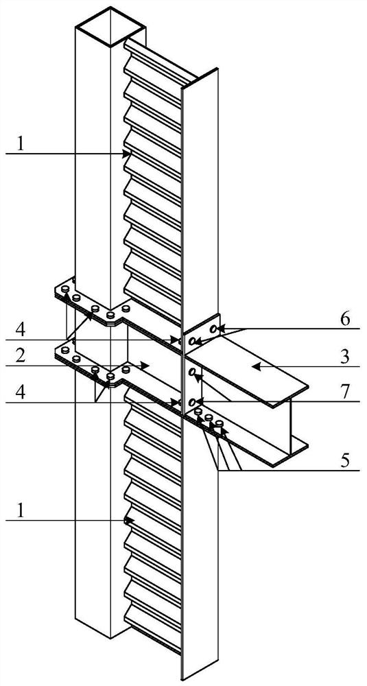
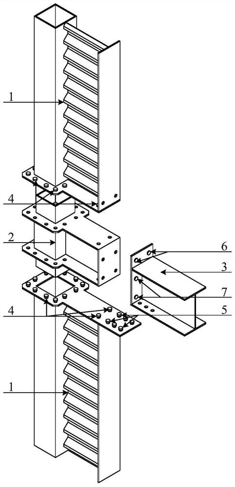
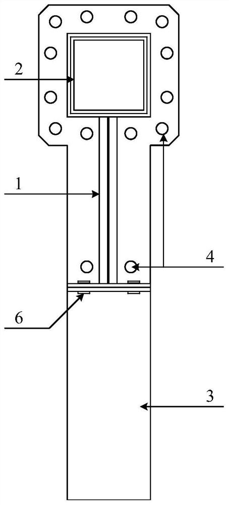
[0024] Attached below Figure 1-9 , detailing the implementation of this patent.

[0025] Such as Figure 1-9 As shown, a prefabricated beam-column connection node based on corrugated plate anti-side special-shaped columns includes the following components:

[0026] 1——corrugated plate anti-side special-shaped column

[0027] 2——Beam-column connection with studs

[0028] 3——I-beam with end plate

[0029] 4——The first high-strength bolt group

[0030] 5——The second high-strength bolt group

[0031] 6——The third high-strength bolt group

[0032] 7——The fourth high-strength bolt group

[0033] 8——Channel steel

[0034] 9——outer flange plate

[0035] 10—Inner flange plate

[0036] 11——corrugated plate

[0037] 12——Flange end plate

[0038] 13——End plate

[0039] 14——I-beam

[0040] 15——The upper steel pipe column

[0041] 16——Chinese steel pipe column

[0042]17——The lower steel pipe column

[0043] 18 - Cantilever beam section with stiffeners

[0044] 19 - flang...


PUM


Abstract

The invention discloses a fabricated beam-column connecting joint based on a corrugated plate anti-side special-shaped column, and belongs to the technical field of structural engineering. The beam-column connecting joint is composed of the corrugated plate anti-side special-shaped column, an I-shaped beam with an end plate, and a beam-column column connecting part with a protruding column. The manufacturing and the welding of steel elements are completed in a factory, so that the welding and the element quality are easy to control; and only steel components need to be hoisted and connected through high-strength bolts on a construction site, so that the construction efficiency is high. According to the fabricated beam-column connecting joint based on the corrugated plate anti-side special-shaped column, the connecting joint has the advantages of mechanical property and practical property at the same time: in the aspect of the mechanical property, the bearing capacity and the lateral stiffness of the special-shaped column are fully utilized, and the connecting joint has good anti-seismic property; and in the aspect of the practical property, a rapid assembly concept is emphaticallyachieved, and the protruding column problem in a house is solved.

Description

technical field [0001] This patent relates to a prefabricated beam-column connection node based on corrugated plate anti-side special-shaped columns, which belongs to the technical field of structural engineering. Background technique [0002] The development of steel structure buildings is closely related to the development of steel structure housing industrialization. To realize the industrialization of steel structure housing requires the standardization of parts and components. At present, high-rise buildings are the main direction of my country's construction industry. Therefore, a method suitable for high-rise buildings is proposed. The new high-efficiency assembled standardized steel structure system and the assembled standardized components based on the new steel structure system are the basis for realizing the industrialization of steel structure housing and promoting the development of steel structure buildings. [0003] At present, there are a large number of welds...

Claims


Application Information

Patent Timeline
Patent Type & Authority Applications(China)
IPC IPC(8): E04B1/24E04B1/58E04C3/32
CPCE04B1/24E04B1/2403E04C3/32E04B2001/2406E04B2001/2415E04B2001/2418E04B2001/2448E04B2001/246E04B2001/2496
Inventor 张爱林李祥源姜子钦王汉文陈鑫
Owner BEIJING UNIV OF TECH
Learn More