Low-coupling transceiving antenna based on coplanar compression type electromagnetic band gap structure

An electromagnetic bandgap structure, transceiver antenna technology, applied in independent non-interaction antenna combination, antenna, antenna coupling and other directions, can solve the problems of complex processing and poor bandgap performance, etc., to increase the difficulty, improve performance, The effect of improving the bandgap performance

Active Publication Date: 2021-01-01
NANJING UNIV OF SCI & TECH
View PDF2 Cites 2 Cited by
  • Summary
  • Abstract
  • Description
  • Claims
  • Application Information

AI Technical Summary

Problems solved by technology

The more widely used two-dimensional electromagnetic bandgap structure is a mushroom-shaped electromagnetic bandgap structure. However, this structure adds metal vias, and the processing is more complicated.
Another two-dimensional electromagne...

Method used


Image

  • Low-coupling transceiving antenna based on coplanar compression type electromagnetic band gap structure
  • Low-coupling transceiving antenna based on coplanar compression type electromagnetic band gap structure
  • Low-coupling transceiving antenna based on coplanar compression type electromagnetic band gap structure

Examples


Embodiment

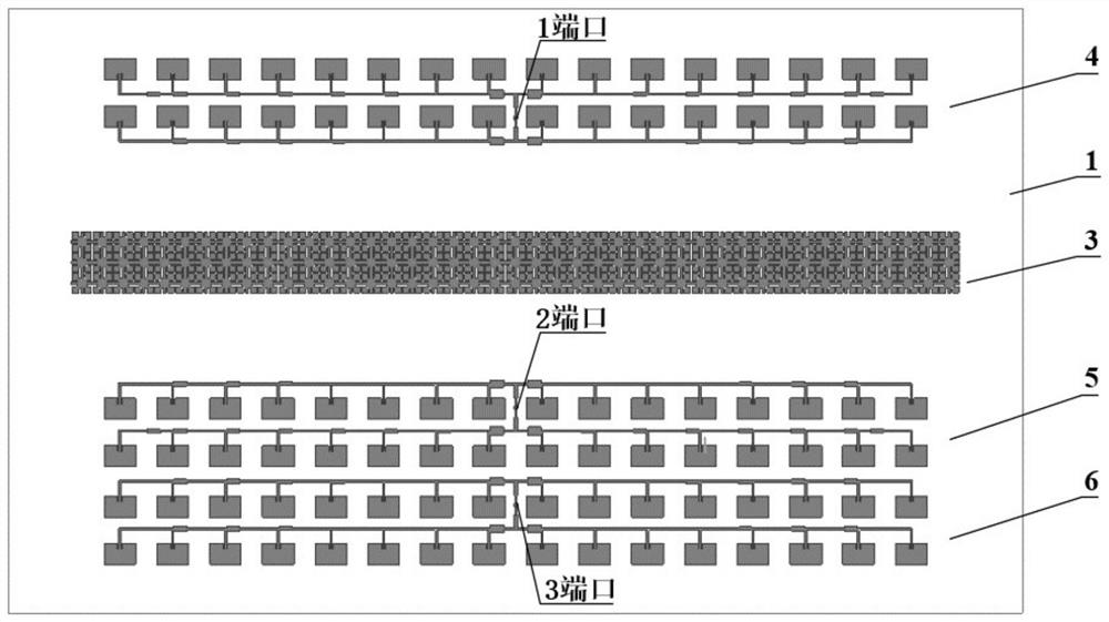
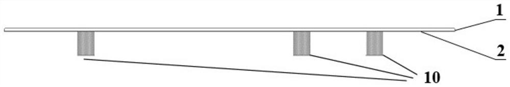
[0028] Such as figure 1 As shown, a low-coupling transceiver antenna based on a coplanar compressive electromagnetic bandgap structure includes a dielectric substrate 1, a periodic metal structure arranged on the upper surface of the dielectric substrate, a metal ground plate 2 arranged at the bottom of the dielectric substrate 1, and a device Transceiver antennas on both sides of the periodic metal structure.

[0029] The dielectric substrate 1 is a Rogers4350B substrate with a dielectric constant of 3.48 and a thickness of 0.508 mm.

[0030] The periodic metal structure is a coplanar compressive electromagnetic bandgap structure 3 closely arranged in n*3, which is formed by connecting a plurality of coplanar compressive electromagnetic bandgap structural units end-to-end through microstrip connecting lines.

[0031] Described transceiver antenna comprises transmitting antenna 4, the first receiving antenna 5 and the second receiving antenna 6, and transmitting antenna 4 is ...


PUM


Abstract

The invention discloses a low-coupling transceiving antenna based on a coplanar compression type electromagnetic band gap structure, and the antenna comprises a dielectric substrate, a transmitting antenna and a receiving antenna which are arranged on the dielectric substrate, a coplanar compression type electromagnetic band gap structure and a metal grounding plate, wherein the transmitting antenna and the receiving antenna are positioned on the dielectric substrate; the antenna system is a one-transmitting and two-receiving system, a transmitting antenna and a receiving antenna are both parallel-feed microstrip array antennas, the coplanar compression type electromagnetic band gap structure and the antenna are located on the same layer and located between the transmitting antenna and thereceiving antenna, and the metal grounding plate is located on the other side of the dielectric substrate. By introducing the coplanar compression type electromagnetic band gap structure, the band elimination characteristic is achieved, the common problem of mutual coupling between transmitting and receiving antennas in a radar system is greatly solved, and the method can be applied to short-range detection radars.

Description

technical field [0001] The invention relates to a low-coupling transceiver antenna, in particular to a low-coupling transceiver antenna based on a coplanar compressed electromagnetic bandgap structure. Background technique [0002] As people have higher and higher requirements for angle measurement of radar systems, one-shot-multiple-receive system or even MIMO system is often required to achieve system performance. At the same time, people's requirements for the miniaturization and integration of electronic equipment have also been further improved, and the distance between the transceiver array antennas has been continuously reduced, and the problem of mutual coupling between antennas has become very prominent. The mutual coupling problem between antennas will not only affect the antenna radiation performance, but also lead to the deterioration of the signal-to-noise ratio of the front end of the equipment, and the performance of the entire radar system will deteriorate sh...

Claims


Application Information

Patent Timeline
IPC IPC(8): H01Q1/52H01Q21/28
CPCH01Q1/525H01Q21/28Y02D30/70
Inventor 胡泰洋周卓辉高晓堃吴礼薛文张晋宇肖泽龙
Owner NANJING UNIV OF SCI & TECH
Why Eureka
Try Eureka