Blast furnace hearth masonry structure for eliminating blast furnace air gap

A technology of masonry structure and blast furnace, which is applied in blast furnace, blast furnace details, blast furnace parts and other directions, can solve the problems of destroying the integrity of the heat transfer system of the hearth, reducing the service life of the blast furnace, and insufficient consolidation strength, and achieves favorable results. Effects of blast furnace longevity, elimination of blast furnace hearth air gaps, and reduction of abnormal erosion

Inactive Publication Date: 2021-01-05
CISDI RES & DEV CO LTD
View PDF6 Cites 2 Cited by
  • Summary
  • Abstract
  • Description
  • Claims
  • Application Information

AI Technical Summary

Problems solved by technology

[0004] In view of this, in order to solve the problem that the tamping layer between the stave and the carbon brick is not strong enough to cause air gaps, damage the integrity of the hearth heat transfer system, and reduce the service life of the blast furnace, the present invention provides a method for eliminating The blast furnace hearth masonry structure of the blast furnace air gap can prevent the hearth air gap, and at the same time reduce the construction difficulty and prevent accidents, which is conducive to alleviating the abnormal erosion of the hearth and prolonging the service life of the blast furnace

Method used


Image

  • Blast furnace hearth masonry structure for eliminating blast furnace air gap
  • Blast furnace hearth masonry structure for eliminating blast furnace air gap
  • Blast furnace hearth masonry structure for eliminating blast furnace air gap

Examples


Embodiment 1

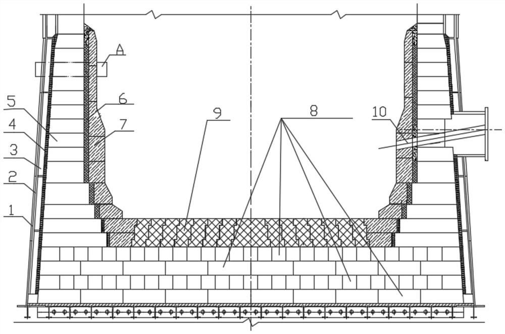
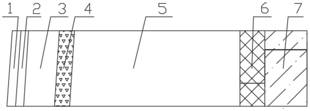
[0027] From the outside to the inside of the hearth of the traditional large carbon brick blast furnace, the side walls are the furnace shell 1, the packing layer 2, the cooler 3, the pounding layer between the carbon brick and the cooler, the large carbon brick 5, the ceramic cup and the charcoal Ramping layer between bricks and ceramic cup7. The function of the pounding layer between the carbon brick and the cooler and between the ceramic cup and the carbon brick is to absorb expansion and fill the gap.

[0028] like Figure 1~2 As shown, the present invention replaces the ramming layer between the carbon brick and the cooler or / and the ramming layer between the ceramic cup and the carbon brick with a high thermal conductivity castable. The furnace hearth side wall of the present invention is successively from the outside to inside the furnace shell 1, the packing layer 2, the cooler 3, the first pouring material layer 4 between the carbon brick and the cooler, the large ca...

Embodiment 2

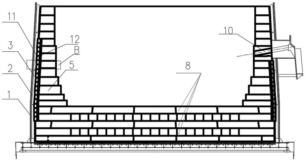
[0031] like Figure 3-4 As shown, the side wall of the traditional small carbon brick + large carbon brick blast furnace hearth is furnace shell 1, packing layer 2, cooler 3, small carbon brick 11, small carbon brick and large carbon brick from outside to inside. Ramping layer between bricks, large charcoal bricks 5. The role of the pounding layer between the small carbon brick and the large carbon brick is to absorb expansion and fill the gap.

[0032]The invention replaces the pounding material layer between the small carbon bricks and the large carbon bricks with high thermal conductivity pouring material. The furnace hearth side wall of the present invention is successively furnace shell 1, packing layer 2, cooler 3, small carbon brick 11, the third pouring material layer 12 between the small carbon brick and the large carbon brick, from outside to inside. Large charcoal bricks 5.

[0033] Due to the limitation of the size of the ramming equipment, etc., the thickness o...


PUM

PropertyMeasurementUnit
thicknessaaaaaaaaaa
thermal conductivityaaaaaaaaaa

Abstract

The invention belongs to the field of blast furnace iron making, and relates to a blast furnace hearth masonry structure for eliminating a blast furnace air gap. The blast furnace hearth masonry structure is divided into a large carbon brick masonry structure and a small carbon brick and large carbon brick masonry structure, a material ramming layer in a traditional blast furnace hearth masonry structure is replaced with a pouring material layer, the thickness of the pouring material layer is less than 40mm, the heat conductivity coefficient of pouring materials in the pouring material layer is greater than 10W / (m.DEG C), and the pouring materials are one or two of CSiC or all-C materials. The problems that due to the fact that the solidification strength of the material ramming layer between a cooling wall and carbon bricks is not enough, the air gap is easy to occur, the integrity of a hearth heat transfer system is damaged, and the service life of a blast furnace is shortened are solved.

Description

technical field [0001] The invention belongs to the field of blast furnace ironmaking, and relates to a blast furnace hearth masonry structure for eliminating air gaps in the blast furnace. Background technique [0002] The blast furnace is the key link with the highest investment and the highest energy consumption in the iron and steel industry. Prolonging the life of the blast furnace plays a vital role in reducing the cost per ton of iron and improving the competitiveness of iron and steel enterprises. Since 2000, my country's iron and steel industry has developed rapidly, and its steel output has grown rapidly, ranking first in the world. However, the current average life of blast furnaces in my country is only 5-10 years, which is far lower than that of foreign countries. The problematic parts of my country's blast furnaces are mainly concentrated in the hearth. Since 2000, according to incomplete statistics, hearth burn-through accidents have occurred in at least 45 ...

Claims


Application Information

Patent Timeline
Patent Type & Authority Applications(China)
IPC IPC(8): C21B7/06
CPCC21B7/06
Inventor 牛群邹忠平赵运建许俊钟星立
Owner CISDI RES & DEV CO LTD
Why Eureka
Try Eureka