
A blast furnace tuyere protection device

A protection device and tuyere technology, applied in the direction of the tuyere, can solve the problems of poor thermal conductivity at the gap of the tuyere, uneven packing density, waste of water loss of the packing, etc., and achieves the effect of saving material consumption, reducing damage, and reducing the probability of damage.

Active Publication Date: 2022-05-06
SHAGANG GROUP +2
View PDF3 Cites 0 Cited by
  • Summary
  • Abstract
  • Description
  • Claims
  • Application Information

AI Technical Summary

Problems solved by technology

However, filling the gaps of the tuyeres in this way often has problems such as water loss and waste of fillers, uneven density of fillers in the gaps, etc.
At the same time, compared with copper staves or cast iron staves with good thermal conductivity, the gaps of the filled tuyere have poorer thermal conductivity and are more prone to damage

Method used


Image

  • A blast furnace tuyere protection device
  • A blast furnace tuyere protection device

Examples


Embodiment 1

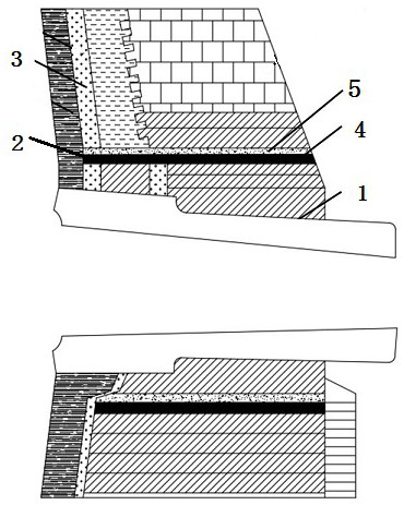
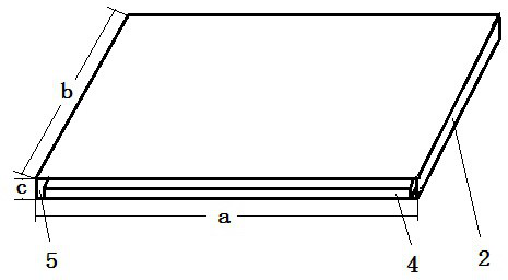
[0019] Such as figure 1 and figure 2 As shown, a blast furnace tuyere protection device, the blast furnace tuyere includes a tuyere composite brick 1 , a tuyere gap 2 and a tuyere stave 3 . The tuyere gap 2 is a cavity structure, which is arranged between the tuyere combined brick 1 and the tuyere cooling wall 3, the length of the tuyere gap 2 is a=1000 mm, the depth is b=140 mm, and the height is c=25mm. The protection device is arranged in the gap 2 of the tuyere, and the protection device includes a heat conduction device 4 and a filling device 5 . The length of the heat conducting device 4 is 995 mm, the depth is 137 mm, and the height is 10 mm. The heat conducting device 4 is a copper sheet with a purity of 99.99%, and the tuyere cooling stave 3 is a cast iron cooling stave, that is, the thermal conductivity of the heat conducting device 4 is greater than that of the tuyere cooling stave 3 . The filling device 5 covers the heat conduction device 4 and adheres to the ...

Embodiment 2

[0023] Such as figure 1 and figure 2 As shown, a blast furnace tuyere protection device, the blast furnace tuyere includes a tuyere composite brick 1 , a tuyere gap 2 and a tuyere stave 3 . The tuyere gap 2 is a cavity structure, which is arranged between the tuyere combined brick 1 and the tuyere cooling wall 3, the length of the tuyere gap 2 is a=1000 mm, the depth is b=150 mm, and the height is c=30mm. The protection device is arranged in the gap 2 of the tuyere, and the protection device includes a heat conduction device 4 and a filling device 5 . The length of the heat conducting device 4 is 1000 mm, the depth is 150 mm, and the height is 15 mm. The heat conducting device 4 is a copper sheet with a purity of 99.99%, and the tuyere cooling stave 3 is a copper cooling stave, that is, the thermal conductivity of the heat conducting device 4 is equal to that of the tuyere cooling stave 3 . The filling device 5 covers the heat conduction device 4 and adheres to the cavity...


PUM

PropertyMeasurementUnit
diameteraaaaaaaaaa
lengthaaaaaaaaaa
depthaaaaaaaaaa

Abstract

The invention discloses a blast furnace tuyere protection device, which belongs to the technical field of blast furnace equipment. The blast furnace tuyere includes a tuyere combination brick, a tuyere gap and a tuyere cooling wall, the tuyere gap is a cavity structure, and is arranged between the tuyere combination brick and the tuyere cooling wall, and the length of the tuyere gap is a, The depth is b, the height is c, the protection device is arranged in the gap of the tuyere, the protection device includes a heat conduction device and a filling device, the length of the heat conduction device is (a‑5 mm)~a, and the depth is ( b-3 mm)~b, the height is (c / 2-5 mm)~c / 2, the thermal conductivity of the heat conduction device is greater than or equal to the thermal conductivity of the cooling wall of the tuyere; the filling device covers the heat conduction The device is attached to the cavity of the air outlet slit. The device can reduce the damage of the tuyeres, increase the cooling speed of the tuyeres of the blast furnace, and prolong the service life of the tuyeres.

Description

technical field [0001] The invention belongs to the technical field of blast furnace equipment, and in particular relates to a blast furnace tuyere protection device. Background technique [0002] The temperature at the blast furnace tuyere is high, and the tuyere is frequently damaged, and the damage is mainly concentrated in the gap between the cooling wall and the tuyere composite brick. In the traditional way, the admixture (concentrate powder or clinker powder) and the binder (high alumina cement) are generally mixed in a certain proportion, then iron filings and water are added for stirring, and then the gaps in the tuyeres are filled. Due to the high aluminum content of high alumina cement in the filling material, it is easy to form slag skin, and the formed slag skin has a protective effect on the gap. However, filling the gaps of the tuyeres in this way often has problems such as water loss and waste of fillers, and uneven density of fillers in the gaps. At the sa...

Claims


Application Information

Patent Timeline
Patent Type & Authority Patents(China)
IPC IPC(8): C21B7/16
CPCC21B7/16
Inventor 杜屏雷鸣张勇张建良马洪佑张华梁晓乾
Owner SHAGANG GROUP
Learn More