Post-tensioning prestressed box girder double-duct type vacuum-assisted mud jacking system and construction method thereof

A vacuum-assisted, prestressed technology, applied in bridges, bridge materials, bridge construction, etc., can solve problems affecting the quality and compactness of grouting, high labor costs, and poor sealing effects

Inactive Publication Date: 2021-01-05
CHINA FIRST METALLURGICAL GROUP
View PDF11 Cites 1 Cited by
  • Summary
  • Abstract
  • Description
  • Claims
  • Application Information

AI Technical Summary

Problems solved by technology

[0002] After the post-tensioned prestressed box girder is poured, the prestressed reinforcement channels and prestressed steel bars will be left, and the prestressed reinforcement channels need to be filled by vacuum-assisted grouting. However, the current vacuum-assisted grouting technology has the following problems: 1) The grouting pump The vacuum equipment and the vacuum equipment are arranged at both ends of the prestressed steel tunnel respectively. The operation and layout are cumbersome, the grouting quality is not easy to control, and the labor cost is high; 2) The prestressed steel tunnel needs to be grouted one by one, and the construction period is slow; 3) The sealing effect Poor, can not prestress the complete vacuum state of the steel channel, affecting the grouting quality and compactness

Method used


Image

  • Post-tensioning prestressed box girder double-duct type vacuum-assisted mud jacking system and construction method thereof
  • Post-tensioning prestressed box girder double-duct type vacuum-assisted mud jacking system and construction method thereof
  • Post-tensioning prestressed box girder double-duct type vacuum-assisted mud jacking system and construction method thereof

Examples


Embodiment Construction

[0025] The present invention will be further described below in conjunction with the accompanying drawings and embodiments.

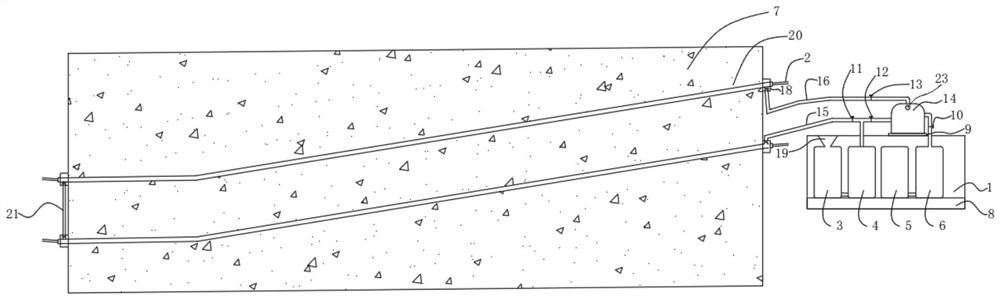
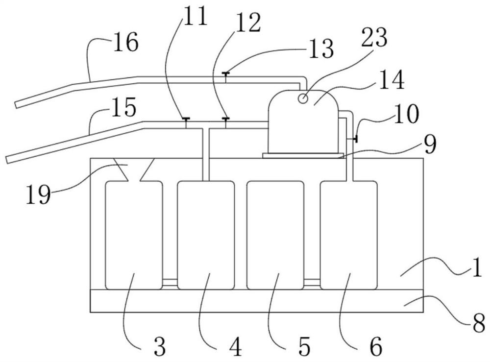
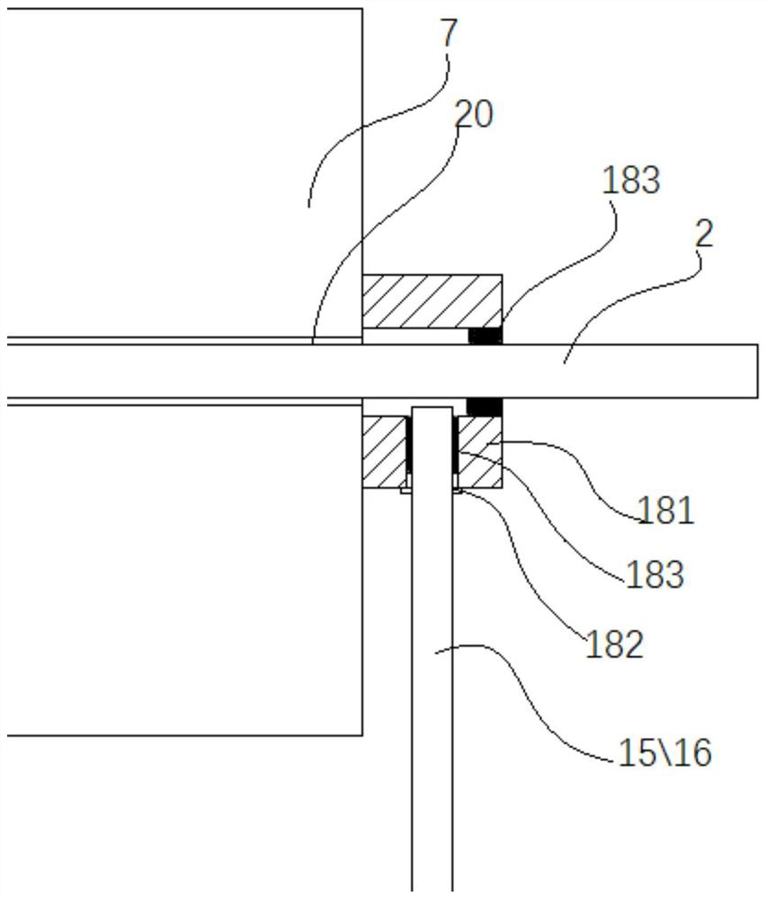
[0026] like figure 1 and figure 2 As shown, a post-tensioned prestressed box girder double-channel vacuum-assisted grouting system includes a vacuum-assisted grouting machine, a sealing assembly 18, a connecting pipe 21 and a vacuum degree measuring piece 22; The two ends of the stress reinforcement channel 20 are closed, the sealing assembly 18 has an external interface connected with the prestressing reinforcement channel 20, and the two ends of the connecting pipe 21 are respectively sealed and connected with the external interfaces at the tail ends of the two prestressing reinforcement channels 20, and the vacuum degree is measured Part 22 is used to measure the vacuum degree of the prestressed steel bar channel 20, and generally adopts a pressure gauge; the vacuum assisted grouting machine includes a mortar mixing chamber 3 with a mortar inlet 19...


PUM


Abstract

The invention discloses a post-tensioning prestressed box girder double-duct type vacuum-assisted mud jacking system and a construction method thereof. A sealing assembly seals the two ends of two prestressed reinforcement ducts respectively, the two ends of a communicating pipe are in sealed connection with the tail ends of the two prestressed reinforcement ducts respectively, and a vacuum degreemeasuring piece is used for measuring the vacuum degree of the prestressed reinforcement ducts; an vacuum-assisted mud jacking machine comprises a mud stirring bin provided with a mud inlet and a stirring mechanism, a mud jacking pump with the inlet connected with the mud stirring bin, a waste mud bin provided with a pressure release valve, a negative pressure bin, and a vacuum pump with the inlet connected with the negative pressure bin. The outlet of the mud jacking pump is divided into two paths, one path is in sealed connection with one prestressed reinforcement hole channel through a mudjacking pipe with a first valve, the other path is communicated with the waste mud bin through a pipeline with a second valve, and the waste mud bin is in sealed connection with the head end of the other prestressed reinforcement hole channel through a vacuum pipe with a third valve. The negative pressure bin is communicated with the waste mud bin through a pipeline with a fourth valve. Double-hole-channel one-time grouting can be achieved, and operation is convenient and fast.

Description

technical field [0001] The invention belongs to the field of engineering construction, and in particular relates to a post-tensioned prestressed box girder double-channel vacuum-assisted grouting system and a construction method. Background technique [0002] After the post-tensioned prestressed box girder is poured, the prestressed reinforcement channels and prestressed steel bars will be left, and the prestressed reinforcement channels need to be filled by vacuum-assisted grouting. However, the current vacuum-assisted grouting technology has the following problems: 1) The grouting pump The vacuum equipment and the vacuum equipment are arranged at both ends of the prestressed steel tunnel respectively. The operation and layout are cumbersome, the grouting quality is not easy to control, and the labor cost is high; 2) The prestressed steel tunnel needs to be grouted one by one, and the construction period is slow; 3) The sealing effect Poor, can not prestress the complete va...

Claims


Application Information

Patent Timeline
Patent Type & Authority Applications(China)
IPC IPC(8): E01D21/00E01D2/04E01D101/28
CPCE01D2/04E01D21/00E01D2101/28
Inventor 孔晓龙李兵王赛魏华杰狄昊陈世伟刘小松樊新通郑秉垚鲁立勇弓建春
Owner CHINA FIRST METALLURGICAL GROUP
Why Eureka
Try Eureka