An automatic batch thermal stripping device for optical fiber coating

A coating and optical fiber technology, which is applied in the field of automatic batch thermal stripping devices for optical fiber coatings in batches, can solve the problems of reducing thermal stripping speed, low safety, etc., avoiding waste of manpower, material resources and time, and simple operation method. , to ensure the effect of clamping consistency

Active Publication Date: 2022-06-28
BEIJING CHANGCHENG INST OF METROLOGY & MEASUREMENT AVIATION IND CORP OF CHINA
View PDF0 Cites 0 Cited by
  • Summary
  • Abstract
  • Description
  • Claims
  • Application Information

AI Technical Summary

Problems solved by technology

However, the methods currently adopted are usually simple fixtures, which are operated manually by a single branch.
This method reduces the speed of thermal stripping, and the operation process involves heated concentrated sulfuric acid, which is not safe

Method used


Image

  • An automatic batch thermal stripping device for optical fiber coating
  • An automatic batch thermal stripping device for optical fiber coating

Examples


Embodiment 1

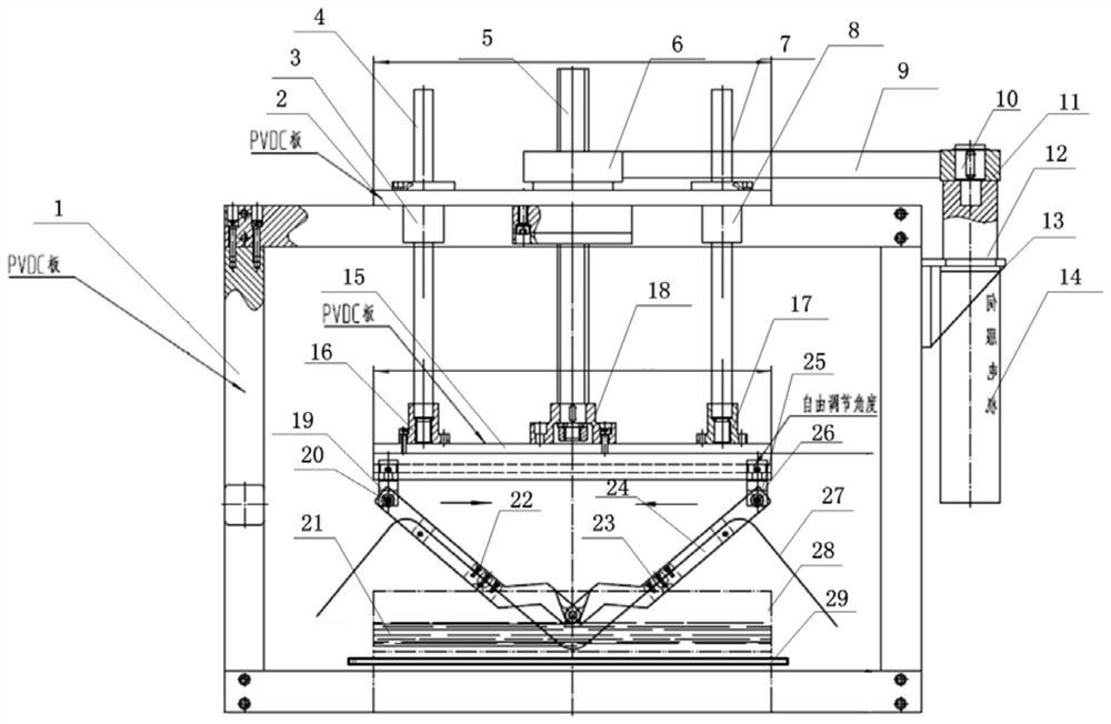
[0037] like figure 2 As shown, this embodiment discloses a batch thermal stripping device for optical fiber coating, including a support frame 1, an upper mounting plate 2, a connecting rod sleeve A3, a connecting rod A4, a lead screw 5, a gear A6, a connecting rod B7, a connecting rod Rod sleeve B8, belt 9, gear B10, coupling 11, reducer 12, motor mounting bracket 13, servo motor 14, lower mounting plate 15, connecting rod mounting seat A16, connecting rod mounting seat B17, screw mounting seat 18. Pin shaft A19, rotation pin A20, acid solution 21, rubber sheet A22, rubber sheet B23, splint frame 24, pin shaft B25, rotation pin B26, optical fiber 27, container 28, heating device 29.

[0038] The main function of the support frame 1 is to support the entire control device.

[0039] The main functions of the upper mounting plate 2 and the lower mounting plate 15 are to install and fix the screw 5, the connecting rod A4, the connecting rod B7, the clamping plate frame 24, and ...


PUM


Abstract

The invention discloses an automatic batch thermal stripping device for optical fiber coating layers, which belongs to the technical field of thermal stripping devices. The present invention includes a support frame, a control system, a main control unit, a movement displacement unit, a mounting panel, a fixture, a liquid immersion unit, and a heating unit; the present invention performs parameter setting and automatic control of the main control unit through the control system, and combines With the cooperation of the device, the optical fiber coating layer can be stripped automatically, quickly and in batches. The stripped length has good consistency and will not cause physical damage to the optical fiber, thus ensuring the high mechanical strength of the optical fiber and the safety of acid. The invention can effectively solve the problem of rapid and batch stripping of optical fiber coating layers, avoid the safety problem of acid used in acid stripping, and especially avoid the waste of manpower, material resources and time caused by one by one acid stripping. The invention is applied to the stripping work of the optical fiber coating layer, and provides effective technical means and methods for batch and fast acid stripping of optical fibers.

Description

technical field [0001] The invention relates to a batch thermal stripping device for automatic batches of optical fiber coating layers, belonging to the technical field of thermal stripping devices. Background technique [0002] Existing optical fiber coating stripping methods are mainly mechanical, chemical immersion pickling and thermal stripping. Mechanical stripping mainly uses wire stripping pliers or blades to cut and strip. This stripping method is easy to cause serious scratches or scratches on the surface of the optical fiber quartz, which affects the mechanical strength and service life of the optical fiber. And this mechanical pickling cannot precisely control pickling length, and usually has poor consistency. Therefore, chemical immersion pickling and thermal stripping are usually used to remove the optical fiber coating. At present, the most common method is to use concentrated sulfuric acid and heat it. This method combines chemical immersion pickling and ther...

Claims


Application Information

Patent Timeline
Patent Type & Authority Patents(China)
IPC IPC(8): G02B6/245
CPCG02B6/245
Inventor 王洋盛晓岩宋昊赵启迪
Owner BEIJING CHANGCHENG INST OF METROLOGY & MEASUREMENT AVIATION IND CORP OF CHINA
Why Eureka
Try Eureka