Upper reflecting layer structure, reactor core structure and high-temperature gas-cooled reactor

A core structure and reflective layer technology, applied in the core structure, upper reflective layer structure, and high-temperature gas-cooled reactor fields, can solve problems such as large flow resistance, no fluid distribution, and undesigned fluid distribution

Pending Publication Date: 2021-01-08
CHINA NUCLEAR POWER ENG CO LTD
View PDF0 Cites 3 Cited by
  • Summary
  • Abstract
  • Description
  • Claims
  • Application Information

AI Technical Summary

Problems solved by technology

[0003] However, in the existing high-temperature gas-cooled reactors, such as the pebble bed high-temperature gas-cooled reactor, although there is an upper reflector layer, the shape is completely different from that of the prismatic graphite block, and it does not have the function of fluid distribution. In the high-temperature gas-cooled reactor, the structure of the upper reflective layer only has the basic function of reflecting neutrons, and the function of fluid distribution is not designed. The co...

Method used


Image

  • Upper reflecting layer structure, reactor core structure and high-temperature gas-cooled reactor
  • Upper reflecting layer structure, reactor core structure and high-temperature gas-cooled reactor
  • Upper reflecting layer structure, reactor core structure and high-temperature gas-cooled reactor

Examples


Embodiment 1

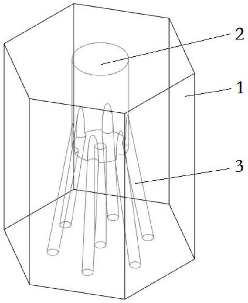
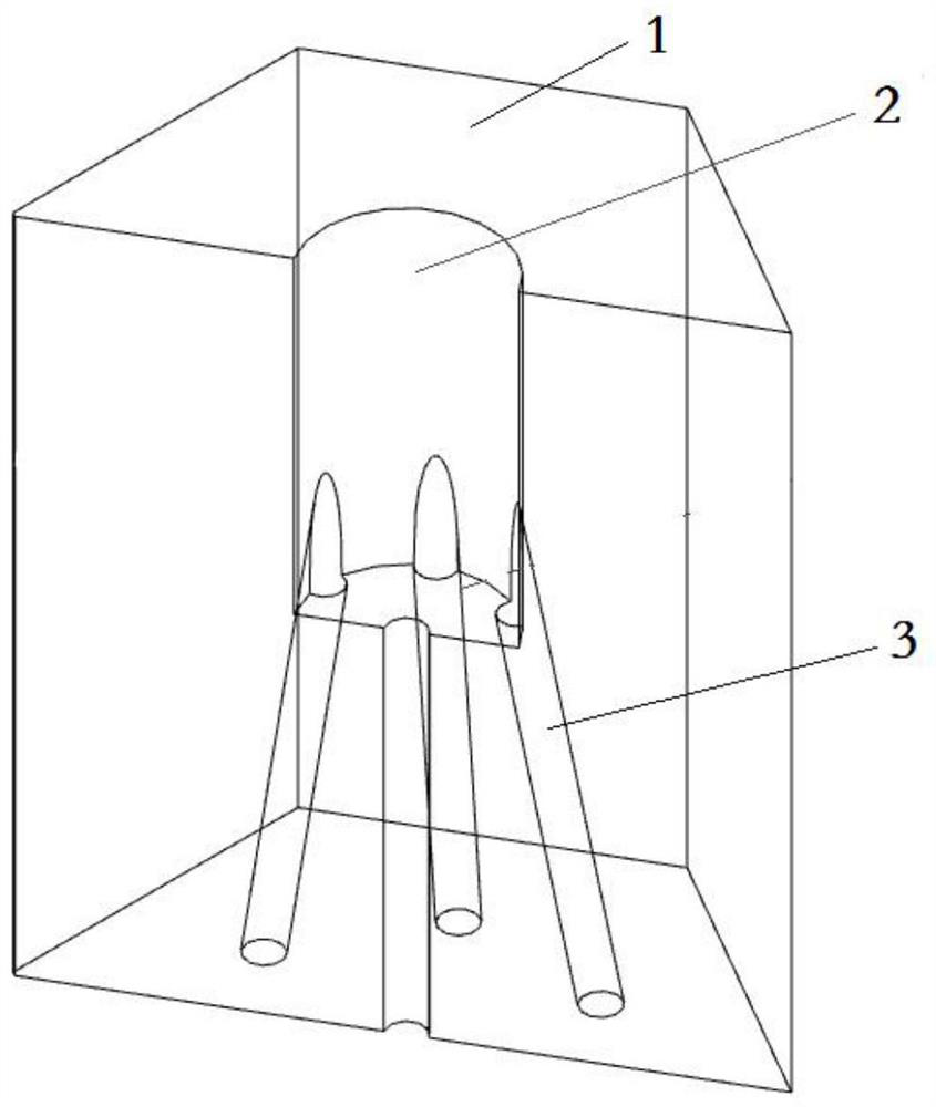
[0035] Such as figure 1 , figure 2 As shown, this embodiment discloses an upper reflective layer structure, which includes a plurality of graphite bricks 1 , and a chamber 2 and a plurality of channels 3 are arranged inside the graphite bricks 1 . The chamber 2 is arranged on the upper part of the graphite brick 1 for circulating coolant. A plurality of passages are arranged at the lower part of the graphite brick 1 , and the entrance of each passage 3 communicates with the chamber 2 , and the outlets of the passages are evenly distributed on the lower end surface of the graphite brick 1 .

[0036] Further, the diameters of the channels 3 on the graphite bricks are the same, so that the coolant can be evenly distributed after passing through the upper reflection layer, so as to ensure the uniformity of the coolant entering the fuel area. Certainly, the diameters of the plurality of channels 3 on each graphite brick in this embodiment may also be unequal, which may be specif...

Embodiment 2

[0043] This embodiment discloses a core structure, which includes a fuel region and an upper reflection layer arranged on the upper part of the fuel region. Multiple coolant channels are arranged in the fuel region, and the upper reflection layer adopts the above-mentioned upper reflection layer structure. The diameter of the chamber 2 and the aperture of the channel 3 on each graphite brick can be determined according to the coolant flow requirement of the corresponding fuel zone.

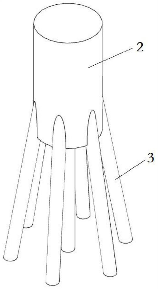
[0044] Further, each channel 3 on each graphite brick is docked or corresponds to each coolant channel on its corresponding fuel zone, for example, there can be 7 (such as image 3 shown), can also be 19 (such as Figure 4 shown) to ensure that coolant can enter the coolant passages that enter the fuel zone through the upper reflector.

[0045] Further, the diameter of each channel 3 of each graphite brick is equal to the diameter of the coolant channel on the corresponding fuel zone to ensure th...


PUM


Abstract

The invention discloses an upper reflecting layer structure. The upper reflecting layer structure is composed of a plurality of graphite bricks, wherein a cavity and a plurality of channels are formedin each graphite brick, and the cavities are formed in the upper portions of the graphite bricks and used for allowing a coolant to circulate; and the plurality of channels are arranged at the lowerparts of the graphite bricks, the inlet of each channel communicates with the corresponding chamber, and the outlets of the channels are uniformly distributed on the lower end surfaces of the graphitebricks. The invention further discloses a reactor core structure adopting the upper reflecting layer structure and a high-temperature gas-cooled reactor. According to the invention, the upper reflecting layer structure can distribute the coolant, so the uniformity of the coolant entering a reactor core fuel area is improved.

Description

technical field [0001] The invention belongs to the field of nuclear technology, and in particular relates to an upper reflection layer structure, a reactor core structure, and a high-temperature gas-cooled reactor. Background technique [0002] In the nuclear industry, the core of the prismatic high-temperature gas-cooled reactor is mainly composed of graphite bricks. The core is arranged neatly and regularly in a prismatic shape. The fuel assembly is layered along its axial direction and arranged in radial divisions in sequence, the upper reflective layer is located at the upper part of the fuel area, and the lower reflective layer is located at the lower part of the fuel area. The core of the high-temperature gas-cooled reactor uses helium as the coolant. After the coolant enters the chamber in the high-temperature gas-cooled reactor, it enters the cooling channel in the fuel assembly in the core through the coolant channel in the upper reflector. , the coolant is gradua...

Claims


Application Information

Patent Timeline
IPC IPC(8): G21C5/02G21C15/02
CPCG21C5/02G21C15/02Y02E30/30
Inventor 董建华张朔婷张成龙姚红朱思阳杨长江贺楷刘国明汪俊
Owner CHINA NUCLEAR POWER ENG CO LTD
Why Eureka
Try Eureka