Coal mill for thermal power plant
A thermal power plant and coal grinding technology, which is applied in the direction of dryers, screens, grilles, etc., can solve the problems of reducing coal grinding efficiency, improve coal grinding efficiency, increase caliber, and save time and manpower for cleaning waste Effect
- Summary
- Abstract
- Description
- Claims
- Application Information
AI Technical Summary
Problems solved by technology
Method used
Image

Examples
Embodiment 1
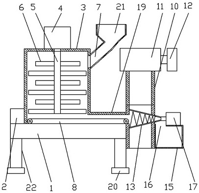
[0025] Such as Figure 1-3 A kind of coal grinding device for a thermal power plant as shown in the embodiment of the present invention includes a workbench 1, a crushing device, a conveying device, an automatic screening air-drying device and a PLC controller 2, and four support columns 22 are fixedly arranged under the workbench 1, The upper surface of the workbench 1 is set as a plane, which is used to carry the crushing device, the conveying device, the automatic screening air-drying device and the PLC controller 2. The crushing device and the PLC controller 2 are arranged on one end of the workbench 1, and the conveying device is arranged under the crushing device. The conveying device is equipped with an automatic screening air-drying device at the end far away from the crushing device.
[0026] Let's talk about the specific settings and effects of its pulverizing device, conveying device, automatic screening air-drying device and PLC controller 2 below.
[0027] The cr...
Embodiment 2
[0032] Such as Figure 1-3 As shown, for the conveyor belt 8, a baffle 19 is provided on the top and both sides of the conveyor belt 8, one end of the baffle 19 is fixedly connected with the outer wall of the crushing chamber 3, and the other end of the baffle 19 is fixedly connected with the outer wall of the air-drying cylinder 9, which can effectively Prevent the outside wind from blowing the coal powder on the conveyor belt 8 away; for the support column 22, rubber pads 20 are fixed under the support column 22, which can play the role of shock absorption and anti-skid; for the feed port 7 , a hopper 21 is fixed on the feed port 7, which can increase the diameter of the feed port 7 and facilitate feeding; for the air preheater 11, the air preheater 11 is installed in the exhaust channel of the boiler, which can The high-temperature flue gas in the flue exhaust channel is used to preheat the air, thereby increasing the effect of drying the pulverized coal.
[0033] In summary...
PUM
 Abstract
Description
Claims
Application Information
 - Generate Ideas
- Intellectual Property
- Life Sciences
- Materials
- Tech Scout
- Unparalleled Data Quality
- Higher Quality Content
- 60% Fewer Hallucinations
Browse by: Latest US Patents, China's latest patents, Technical Efficacy Thesaurus, Application Domain, Technology Topic, Popular Technical Reports.
© 2025 PatSnap. All rights reserved.Legal|Privacy policy|Modern Slavery Act Transparency Statement|Sitemap|About US| Contact US: help@patsnap.com