Intelligent dedusting environment-friendly equipment and working method thereof

An environmental protection equipment and filter box technology, applied in chemical instruments and methods, mixing methods, separation methods, etc., can solve the problems of shortening the service life of the filter element, large dust, inconvenient centralized collection, etc. Effect

Active Publication Date: 2021-01-15
山东瀚江环保科技有限公司
View PDF5 Cites 9 Cited by
  • Summary
  • Abstract
  • Description
  • Claims
  • Application Information

AI Technical Summary

Problems solved by technology

[0003] The existing dust removal equipment has the following disadvantages in use: 1. Due to the problem of large dust in the external environment, the existing filter media often only use filter elements, so in the case of large dust, it is easy to shorten the use of filter elements 2. After the dust is filtered, it cannot be c

Method used


Image

  • Intelligent dedusting environment-friendly equipment and working method thereof
  • Intelligent dedusting environment-friendly equipment and working method thereof
  • Intelligent dedusting environment-friendly equipment and working method thereof

Examples


Embodiment 1

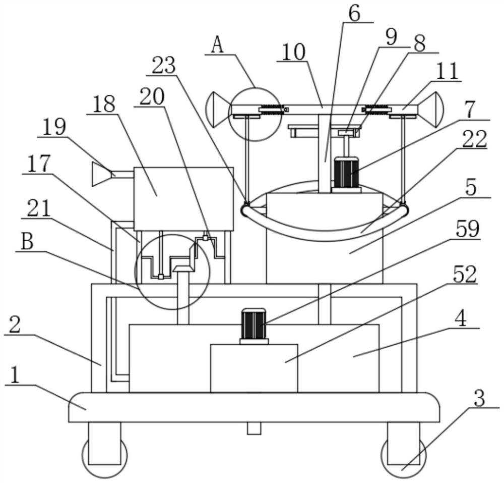
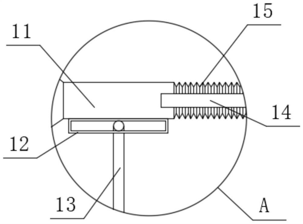
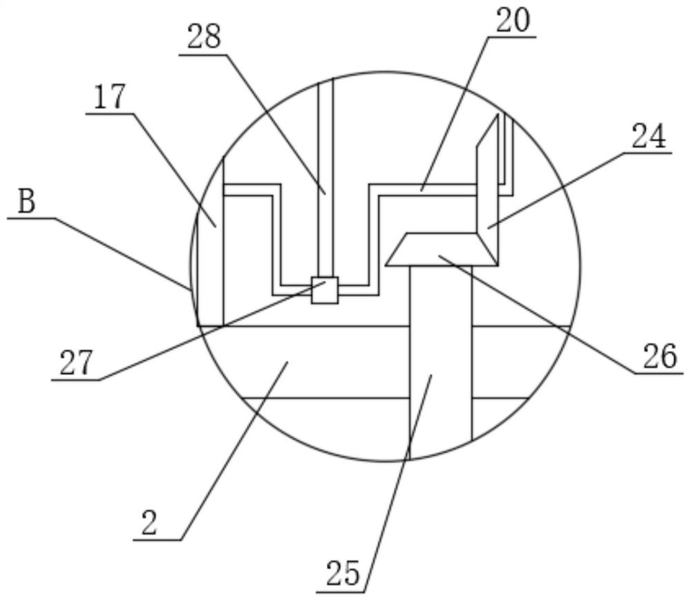
[0046] Embodiment one: if Figure 1-12 As shown, an intelligent dust removal and environmental protection equipment includes a base 1, wheels 3 are arranged on the four corners of the bottom of the base 1, and a mounting frame 2 and a first filter box 4 are respectively fixedly installed on the top of the base 1. The first filter box 4 is provided with water, and the first filter box 4 is located in the installation frame 2, the top side of the installation frame 2 is fixedly installed with the second filter box 5, and the top inner wall of the second filter box 5 is sealed and rotatably connected with a support pipe 6. The top of the support pipe 6 extends to the top of the second filter box 5 and is fixedly connected with the installation pipe 10, and the installation pipe 10 is connected with two nozzle pipes 11 for symmetrical rotation, and the installation pipe 10 is respectively connected with the two nozzle pipes 11 Through, the second filter box 5 is provided with a tr...

Embodiment 2

[0061] Embodiment two: if Figure 13-15 As shown, an intelligent dust removal and environmental protection equipment, the difference between this embodiment and the first embodiment is that the filter press assembly includes an electric push rod 59 fixedly installed on the top of the fixed box 52, and the bottom end of the electric push rod 59 extends to the press A pressure plate 61 is fixedly installed in the filter box 56, and a filter screen 62 below the pressure plate 61 is fixedly installed on the inner wall of the filter press box 56, and the output shaft of the electric push rod 59 is fixedly connected with the top of the pressure plate 61, and the filter press box 56 A drainpipe 57 is fixedly installed on the bottom inner wall of the first filter box 4, and the bottom end of the drainpipe 57 runs through the base 1 and extends to the bottom of the base 1. A water supply pipe 60 is fixedly installed on the bottom inner wall of the first filter box 4, and the water suppl...


PUM


Abstract

The invention discloses intelligent dedusting environment-friendly equipment and a working method thereof. The intelligent dust removal environment-friendly equipment comprises a base, wheels are arranged at the four corners of the bottom of the base correspondingly, a mounting frame and a first filtering box are fixedly mounted at the top of the base, water is contained in the first filtering box, and the first filtering box is located in the mounting frame; and a second filtering box is fixedly mounted on one side of the top of the mounting frame, a supporting pipe is rotatably connected tothe inner wall of the top of the second filtering box in a sealed mode, and the top end of the supporting pipe extends to the position above the second filtering box and is fixedly connected with a mounting pipe. Dust in gas can be conveniently filtered in advance so that the dust attachment amount on the filter element can be reduced, the service life of the filter element can be effectively prolonged, the filtered gas can be quickly diffused, good practicability is achieved, meanwhile, dust in air can be collected in a centralized mode, and thus the equipment has good convenience in use.

Description

technical field [0001] The invention relates to the technical field of environmental protection machinery, in particular to an intelligent dust removal environmental protection equipment and a working method thereof. Background technique [0002] Environmental protection equipment refers to mechanical products, structures and systems manufactured and constructed by production units or construction installation units for controlling environmental pollution and improving environmental quality. Some people also think that environmental protection equipment refers to mechanically processed products to control environmental pollution, such as dust collectors, welding fume purifiers, monomer water treatment equipment, noise controllers, etc. This understanding is not comprehensive. Environmental protection equipment should also include power equipment for transporting fluids containing pollutants, such as water pumps, fans, conveyors, etc.; it also includes monitoring and control ...

Claims


Application Information

Patent Timeline
IPC IPC(8): B01D50/00B01D46/42B01F3/04B01F7/30B01D19/00B01D36/00
CPCB01D19/0052B01D47/08B01D46/00B01D47/02B01D29/03B01D29/82Y02A50/2351
Inventor 不公告发明人
Owner 山东瀚江环保科技有限公司
Why Eureka
Try Eureka