
Ultraviolet laser optical fiber ozone generator

An ozone generator and ultraviolet laser technology, applied in the field of chemical equipment generators, can solve the problems of insufficient ultraviolet light intensity, limited reaction contact surface, high energy consumption, etc.

Pending Publication Date: 2021-01-15
SHAANXI RES DESIGN INST OF PETROLEUM CHEM IND
View PDF0 Cites 0 Cited by
  • Summary
  • Abstract
  • Description
  • Claims
  • Application Information

AI Technical Summary

Problems solved by technology

At present, the ultraviolet ozone generator has high energy consumption and low ozone concentration due to insufficient ultraviolet light intensity and limited reaction contact surface.

Method used


Image

  • Ultraviolet laser optical fiber ozone generator
  • Ultraviolet laser optical fiber ozone generator

Examples


Embodiment Construction

[0023] The present invention is further described below in conjunction with accompanying drawing.

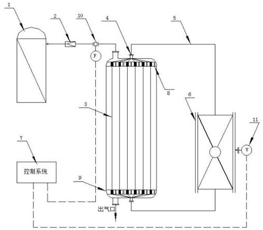
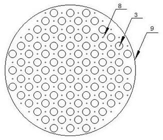
[0024] like figure 1 Shown, a kind of ultraviolet laser optical fiber ozone generator comprises oxygen tank 1, is characterized in that, is provided with decompression valve 2 and flow transmitter 10 on the communicating pipeline between oxygen tank 1 and ozone generator 3; 3 The fiber coupler 4 at the upper end is connected to the ultraviolet laser light source 6 through the conductive optical fiber 5, and the lower end is connected to the dispersion optical fiber in the ozone generator; one end of the ultraviolet laser light source 6 is connected to the control system 7 through the voltage regulator 11; the flow transmitter 10 is connected to the control system 7. An optical fiber fixing plate 9 is provided on the upper and lower sides of the ozone generator 3, the optical fiber fixing plate 9 is provided with a gas channel 8, and the bottom of the ozone generator 3 is provide...


PUM

PropertyMeasurementUnit
Diameteraaaaaaaaaa
Surface areaaaaaaaaaaa

Abstract

The invention discloses an ultraviolet laser optical fiber ozone generator, which is characterized in that a pressure reducing valve and a flow transmitter are arranged on a communication pipeline between an oxygen tank and an ozone generator, an optical fiber coupler at the upper end of the ozone generator is connected with an ultraviolet laser light source through a conduction optical fiber, thelower end of the ozone generator is communicated with a dispersion optical fiber in the ozone generator, one end of the ultraviolet laser source is connected with a control system through a voltage regulator, the flow transmitter is connected with the control system, the upper portion and the lower portion of the interior of the ozone generator are each provided with a dispersion optical fiber fixing plate, gas channels are formed in the optical fiber fixing plates, and a gas outlet is formed below the ozone generator. During working, pure oxygen is decompressed and enters the ozone generator, the oxygen is distributed through the optical fiber fixing plates and enters the ultraviolet laser excitation chamber, ultraviolet laser radiates ultraviolet light to the periphery through the dispersion optical fiber, the oxygen absorbs the energy of the ultraviolet light to become oxygen monons, and the oxygen monons are combined with the oxygen atoms to produce ozone. According to the device,the illumination contact area is increased, light distribution is more uniform, mass transfer limitation is reduced, and the light utilization rate is remarkably increased.

Description

technical field [0001] The invention belongs to the technical field of chemical equipment generators, in particular to an ultraviolet laser optical fiber ozone generator. Background technique [0002] The oxidation-reduction potential of ozone is second only to fluorine gas. Because of this characteristic, ozone can be used in disinfection, sterilization, decolorization, waste gas and water treatment, etc. In recent years, especially under the global epidemic situation, the demand for ozone generators has greatly increased, but the ozone generators on the market have not been subdivided, household, commercial, and industrial have not been fully developed, and the structure of the ozone generator itself needs to be improved. [0003] There are generally three ways to generate ozone: high-voltage discharge, electrolysis and ultraviolet irradiation. The high-voltage discharge ozone generator uses a certain frequency of high-voltage current to create a high-voltage corona elect...

Claims


Application Information

Patent Timeline
IPC IPC(8): C01B13/10
CPCC01B13/10
Inventor 田磊李梦君孙凌凌
Owner SHAANXI RES DESIGN INST OF PETROLEUM CHEM IND
Learn More