

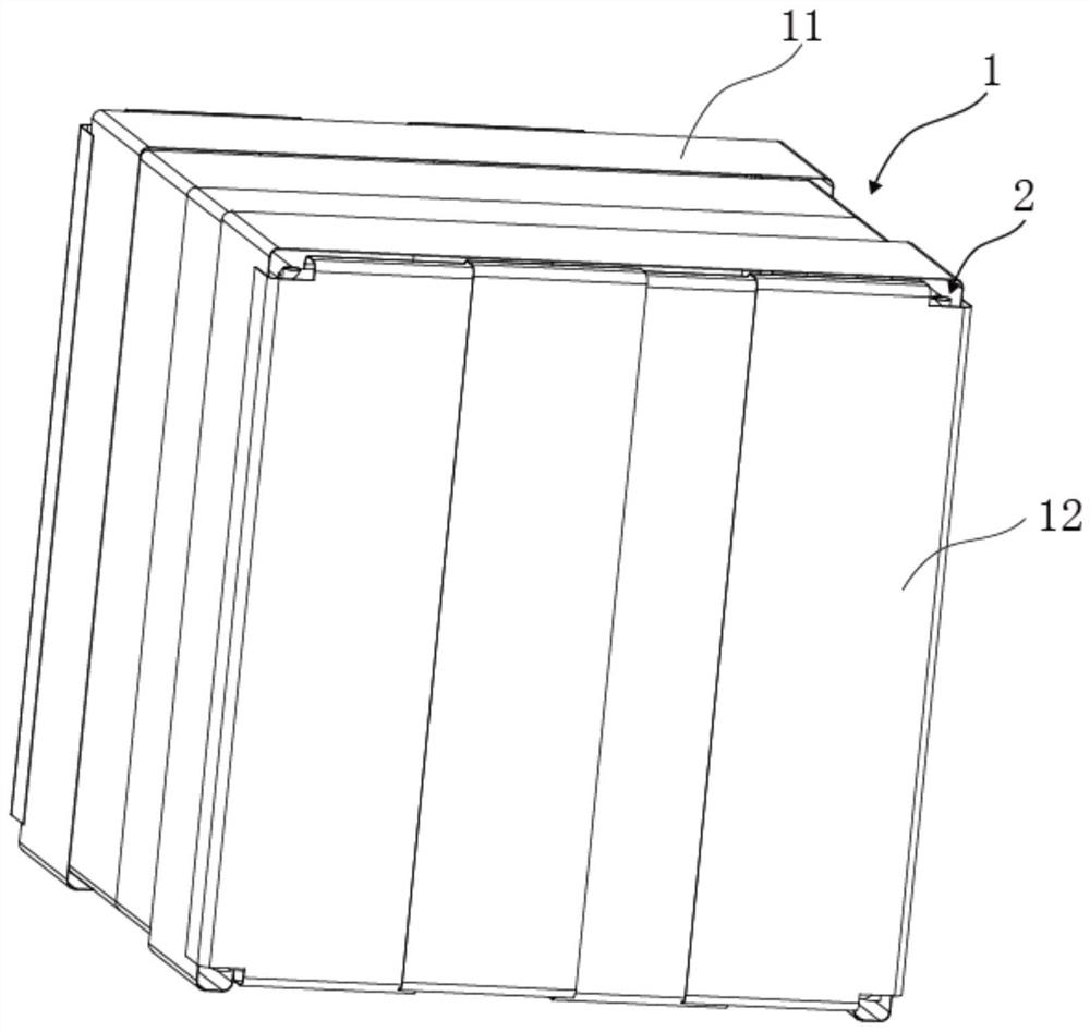
Operation shed for nuclear power equipment maintenance
An equipment and operation technology, applied in small buildings and other directions, can solve the problems of inconvenient portability and turnaround use, inconvenient operation of protective sheds, low efficiency, etc., and achieve the effect of improving work efficiency, quick disassembly, and easy portability.
- Summary
- Abstract
- Description
- Claims
- Application Information
AI Technical Summary
Problems solved by technology
Method used
Image

Examples
Embodiment approach
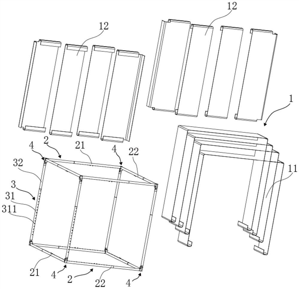
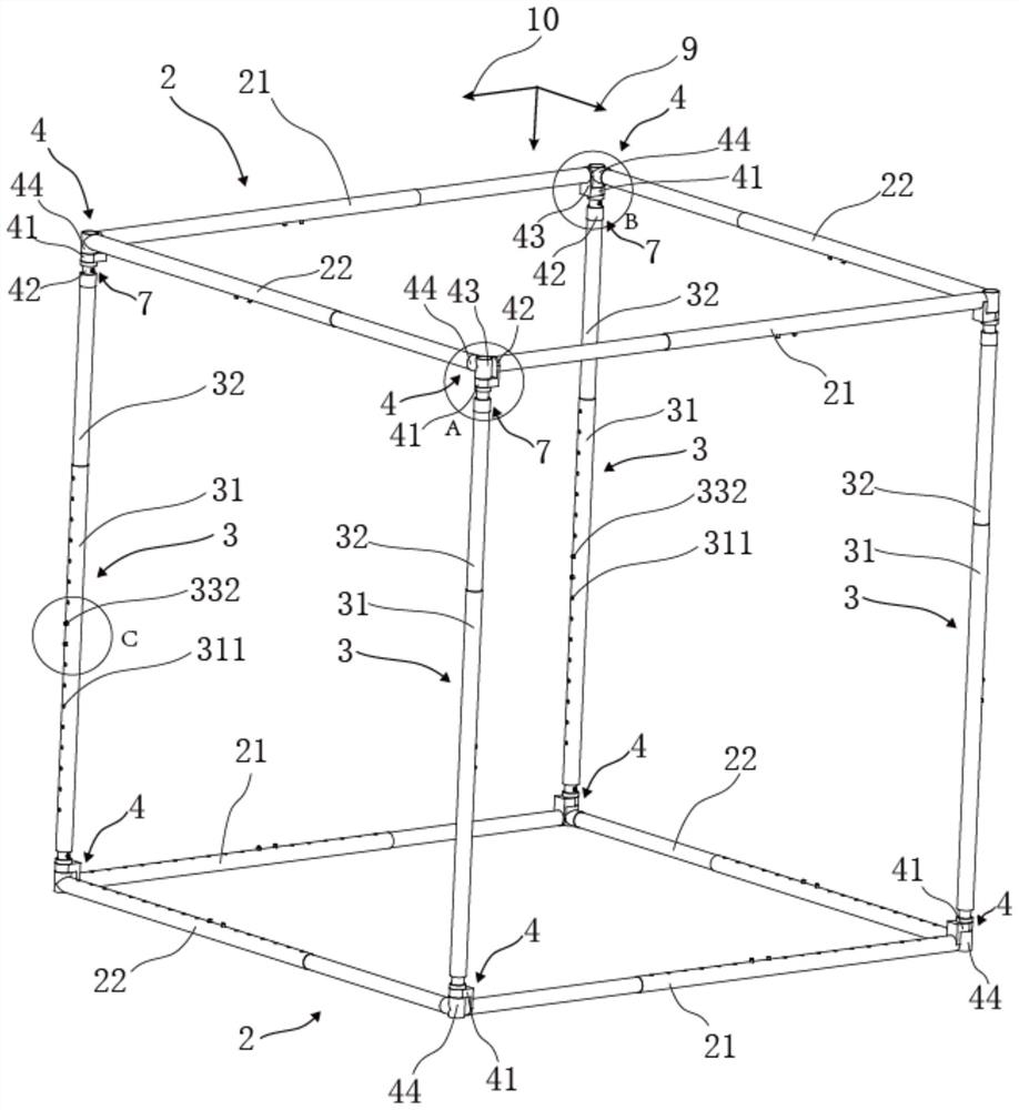
[0057] Specifically, please also refer to image 3 , Figure 4 and Figure 5, as a specific embodiment of the working shed for maintenance of nuclear power equipment provided by the present invention, each vertical telescopic rod 3 includes an outer sleeve 31, an inner sleeve 32 slidingly arranged in the outer sleeve 31, and an inner sleeve 32 for positioning A positioning mechanism 33 for axially moving the inner sleeve 32 in the outer sleeve 31 . When in use, the inner sleeve 32 moves axially in the outer sleeve 31, and then the positioning mechanism 33 is used to position the axial movement position of the inner sleeve 32 in the outer sleeve 31, so as to conveniently adjust the awning. The height of the body skeleton.
specific Embodiment approach
[0058] Please also refer to Figure 4 , Figure 5 and Figure 6 , as a specific embodiment of the working shed for maintenance of nuclear power equipment provided by the present invention, each positioning mechanism 33 includes an elastic member 331 installed in the inner sleeve 32 and a positioning column 332 with one end supported on the elastic member 331 , the inner sleeve 32 is provided with a through hole 321 for the other end of the corresponding positioning column 332 to extend out of the inner sleeve 32, and the outer sleeve 31 is provided with positioning holes for the positioning column 332 to extend into at intervals along its axial direction. Hole 311.
[0059] In this embodiment, each inner sleeve 32 is provided with a positioning mechanism 33 , and each outer sleeve 31 is sequentially provided with positioning holes 311 that cooperate with corresponding positioning columns 332 to lock the corresponding inner sleeve 32 at intervals along its axial direction. W...
PUM
 Abstract
Description
Claims
Application Information