Direct-vision induced abortion uterine curettage device and system

A flow and power system technology, applied in medical science, surgery, diagnosis, etc., can solve the problems of invisibility, incomplete flow, accidental damage to the uterine fundus, etc., and achieve the effect of safe clinical use, avoiding incomplete flow, and avoiding accidental injury

Pending Publication Date: 2021-01-22
GUANGZHOU T K MEDICAL INSTR
View PDF0 Cites 4 Cited by
  • Summary
  • Abstract
  • Description
  • Claims
  • Application Information

AI Technical Summary

Problems solved by technology

[0004] In the direct-viewing flow device of the prior art, the lens module is placed at the front end of the direct-viewing flow device. After finding the embryo implantation tissue through the camera lens, the negative pressure suction port located at the rear end of the camera is used to attract the implanted embryo tissue, and then The detachment of the implanted embryo is completed by repeated insertion and insertion of the artificial flow tube. Because the camera is located at the front end, the specific process of the detachment of the embryo from the implantation site is still invisible during the clinical operation of the direct-viewing artificial abortion device of the prior art. Clinically, there is a risk of incomplete abortion
In addition, since the lens module itself has a certain height, there is a distance of at least 8mm from the negative pressure suction port. Therefore, for the implanted embryos near the entrance of the fallopian tube, that is, near the fundus of the uterus, it is difficult for the direct-viewing artificial abortion device of the prior art. In addition, if the insertion depth of the artificial flow tube is too large, it is easy to cause accidental damage to the fundus of the uterus, and even cause serious consequences of uterine perforation

Method used


Image

  • Direct-vision induced abortion uterine curettage device and system
  • Direct-vision induced abortion uterine curettage device and system
  • Direct-vision induced abortion uterine curettage device and system

Examples


Embodiment 1

[0081] Embodiment 1: The direct-viewing flow curettage device of the present invention with a spatula

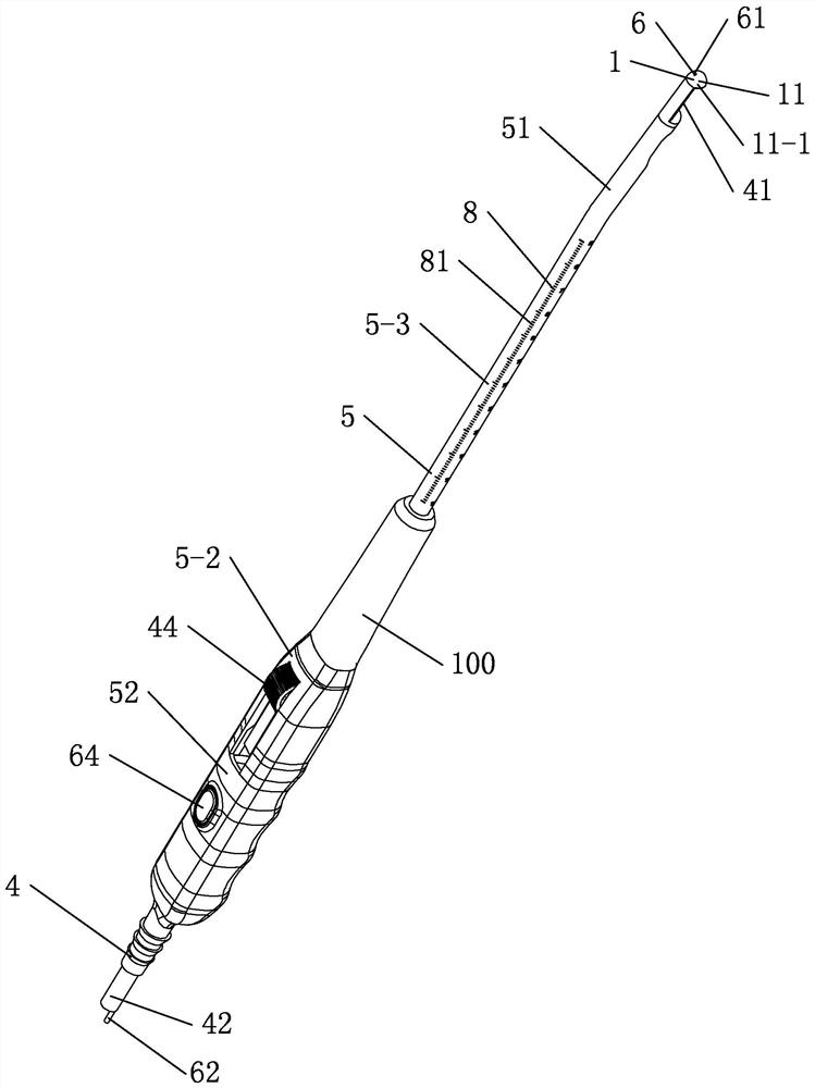
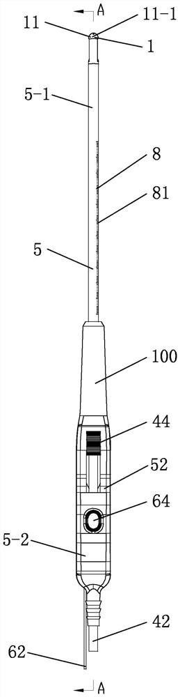
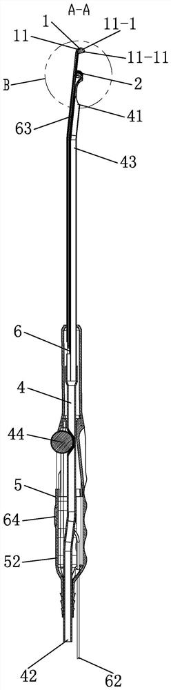
[0082] refer to Figure 1 to Figure 1-4 , The direct-viewing curettage device of the present embodiment includes a curettage mechanism 1, an observation mechanism 2, a circuit 3, a negative pressure suction mechanism 4, and an operating rod 5.

[0083] The curettage mechanism 1 includes at least one curette 11 , and the curettage 11 is arranged at the front end of the operating rod 5 and within the field of view of the observation mechanism 2 .

[0084] The observation mechanism 2 includes an illumination module 21, a lens module 22 and a signal processing module 23; in the light field of the illumination module 21, images and videos observed by the lens module 22 pass through the signal processing module 23 After processing, it is output by the circuit 3.

[0085] Described negative pressure suction mechanism 4 comprises suction inlet 41, suction outlet 42 and suction cha...

Embodiment 2

[0103] Embodiment 2: The direct-viewing flow curettage device of the present invention with a scraper cup

[0104] refer to Figure 2 to Figure 2-3 , The difference between this embodiment and the embodiment is that in this embodiment, the curette 11 is a scraper cup 11-2.

[0105] The front end of the scraper cup 11-2 is blunt, and contains at least one scraping strip 11-21 around it. The blunt head design can ensure that the scraper cup 11-2 will not cause accidental injury to the tissue at the front end of the scraper cup 11-2 during the forward movement process. In clinical use, the scraper strip 11-2 21 It is convenient to scrape the implanted embryonic tissue from the uterus.

[0106] refer to Figure 2-2 and Figure 2-3 , in the present embodiment, the front end of the scraper cup 11-2 is a scraper table 11-23 provided with a through hole 11-22. The scraper cup 11-2, the scraper table 11-23 also rotates accordingly, can scrape the embryonic tissue from the fundus o...

Embodiment 3

[0109] Embodiment 3: The direct-viewing flow curettage device of the present invention with scraping net

[0110] refer to Figure 3 to Figure 3-4 , The difference between this embodiment and Embodiment 1 is that in this embodiment, in this embodiment, the curettage device 11 is a scraping net 11-3.

[0111] In this embodiment, the curette 11 of the curettage mechanism 1 is a scraper 11-3. The camera 22-1 can directly observe the situation behind the scraping screen 11-3 from the mesh gap, even if the scraping screen 11-3 is not made of transparent materials, it can realize the whole process of operation observation and the monitoring of the operation area. Panoramic observation.

[0112] refer to image 3 , in this embodiment, the curettage 11-3 of the curettage device 11 of the curettage mechanism 1 can be compressed in the outer sheath 5-0, when the constraint of the outer sheath 5-0 is removed backward , the scraping screen 11-3 can completely restore or basically rest...


PUM


Abstract

The invention discloses a direct-vision induced abortion uterine curettage device. The device comprises a uterine curettage mechanism, an observation mechanism, a circuit, a negative pressure suctionmechanism and an operation rod. A curettage device of the uterine curettage mechanism is arranged at the front ends of the operation rod and a camera and located in the view of the camera. According to the technical scheme that the camera is arranged on the rear portion, the curettage device is completely located in the view of the camera, the whole operation process can be visible, and no observation dead zone exists. Meanwhile, the curettage device cannot have operation dead corners due to shielding generated by the height of a lens module, embryo tissue can be completely removed when implanted at any position of the uterus, especially for the implantation position near the fallopian tube orifice, namely the bottom of the uterus, the curettage device can easily remove the embryo tissue,and the clinical use process is safer and more efficient. A direct-vision induced abortion uterine curettage system comprises the direct-vision induced abortion uterine curettage device, operation canbe carried out under real-time display of a display system, and the induced abortion operation process is very accurate, safe and efficient.

Description

technical field [0001] The invention relates to an endoscopic surgical instrument, in particular to a curettage device and system for direct-viewing abortion in endoscopic surgery. Background technique [0002] Abortion refers to the use of surgical methods to terminate pregnancy. Abortion surgery methods usually include negative pressure aspiration and forceps curettage. The embryonic tissue in the uterus is sucked out with a straw or the embryonic tissue in the uterus is taken out with surgical instruments such as oval forceps to achieve the purpose of terminating pregnancy. Therefore, the core of abortion surgery lies in two aspects: one is that the embryonic tissue needs to be cleaned up to prevent incomplete abortion; the other is to prevent accidental damage to the uterus during the operation, such as accidental perforation of the uterus. [0003] Because the abortion operation needs to be operated in the uterus, the traditional abortion operation often relies on the ...

Claims


Application Information

Patent Timeline
Patent Type & Authority Applications(China)
IPC IPC(8): A61B17/42A61B17/3207A61B17/32
CPCA61B17/42A61B17/320708A61B17/320016A61B2017/4216A61B2217/005A61B1/05A61B2217/007A61B90/37A61B90/361A61B2090/372A61B2090/309G02B27/0018A61B1/06A61B1/015A61B1/00094A61B5/4325A61B2560/0487
Inventor 周星苏文宇徐华苹罗丽飞王玉娥张琪
Owner GUANGZHOU T K MEDICAL INSTR
Why Eureka
Try Eureka