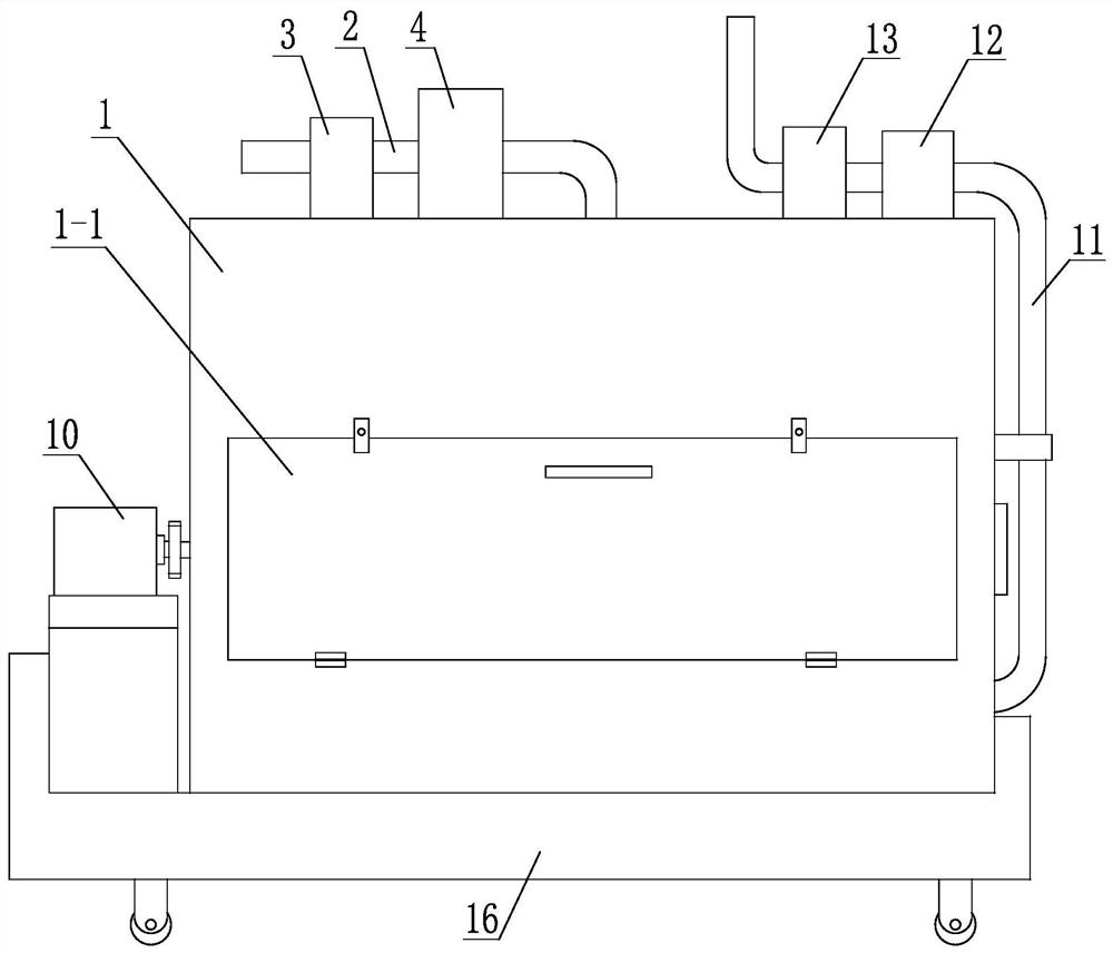
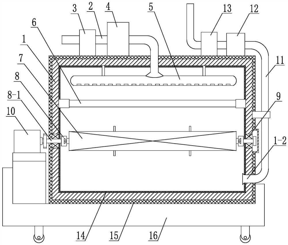
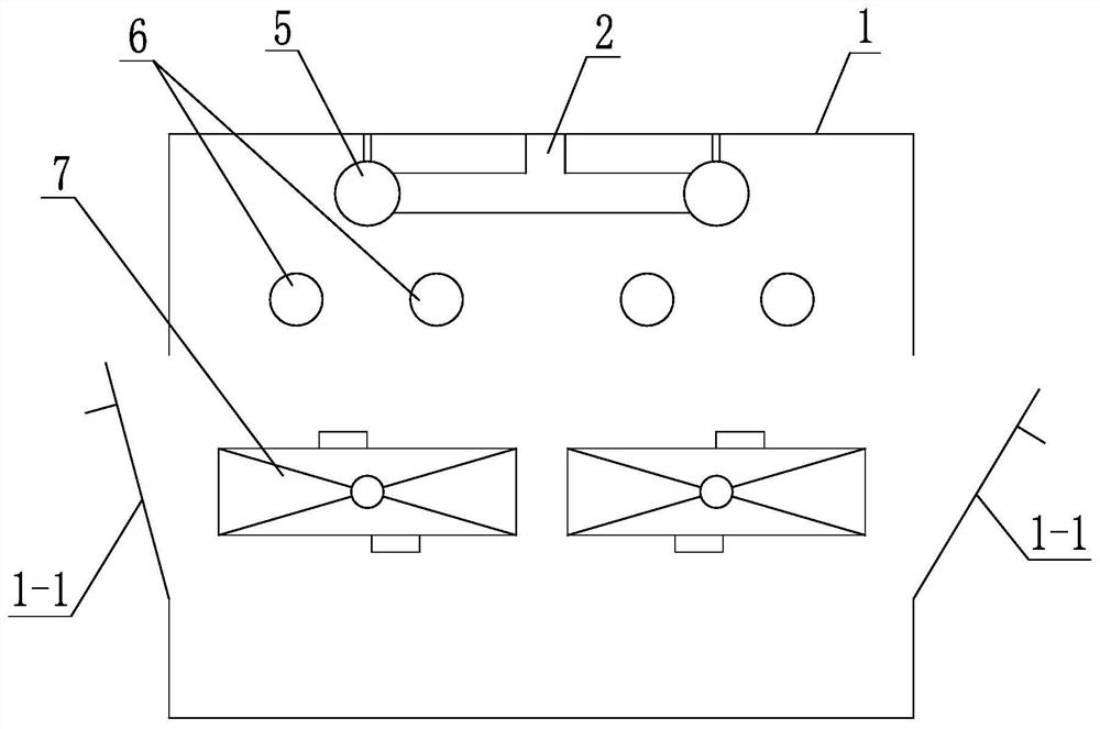
[0017] A high-efficiency baking device for processing electronic components, such as figure 1 , figure 2 , image 3 As shown, it includes an oven 1, the front and/or back of the oven 1 is provided with a door 1-1, an air inlet duct 2 is installed on the top of the oven 1, and an air filter I3, an induced draft fan are connected to the air inlet duct 2 I4, the air outlet of the air inlet pipe 2 enters the inner cavity of the oven 1 through the top of the oven 1, and is communicated with at least one air blowing pipe 5. 1 parallel, the pipe wall of the air blowing pipe 5 is evenly provided with a plurality of air holes, and at least one electric baking pipe 6 which is axially parallel to the air blowing pipe 5 and has a similar length is arranged below the air blowing pipe 5. Below the tube 6 is arranged a wire mesh box 7 positioned and supported by the clip 8. The wire mesh box 7 is axially parallel to the electric baking tube 6 and the axial lengths of the two are similar. A wire mesh box 7 is connected by a pair of clips. The two clamps 8 are located at the two shaft ends of the wire mesh box 7 respectively. The clamps 8 are provided with clamping grooves, and the two shaft ends of the wire mesh box 7 are respectively provided with elastic buckles. The clip is engaged with the slot on the clip 8. The clip 8 is provided with a rotating shaft 8-1, and the rotating shaft is supported and positioned by a bearing 9 arranged on the side wall of the oven 1. One of the pair of clips 8 One of the rotating shafts 8-1 is connected with the output shaft of the geared motor 10 in a driving connection, and an exhaust port 1-2 is provided at the position near the bottom of the side wall of the oven 1. The pipe 11 is connected with an induced draft fan II12 and an air filter II13.
[0018] The inner wall of the oven 1 is provided with a high temperature resistant reflective film 14 (commonly used materials in the market, such as aluminum foil, etc.) to reflect the thermal radiation emitted by the electric oven 6, improve heat utilization, speed up baking and save energy.
[0019] Both the front and the back of the oven 1 are provided with a box door 1-1, two air blow pipes 5 in the oven are arranged in parallel, and a group of parallel air blow pipes 5 and similar lengths are arranged below each air blow pipe 5. As for the electric oven tubes 6 , the number of electric oven pipes in each group of electric oven pipes 6 is 1-3, and a wire mesh box 7 positioned and supported by the clamper 8 is arranged under each group of electric oven pipes 6 .
[0020] The outer wall of the oven 1 is covered with a thermal insulation material layer 15 (a thermal insulation material commonly used in the market) for thermal insulation, energy saving and thermal insulation and anti-scalding.
[0021] The device also has a universal wheel cart 16 that carries the oven 1, the deceleration motor 10 and other corresponding components, so as to facilitate the movement of the device.
[0022] The wire mesh box 7 of the high-efficiency baking device for processing electronic components is a transparent box made of wire mesh, which is air-permeable, water-permeable and heat-permeable, and has a box cover for containing the electronic components to be baked. , the screen box 7 is generally configured with a plurality of them for alternate use; while the baking device is running, it can load components on other screen boxes 7 to save time, and wait for the components loaded in the previous screen box 7 After the baking process is completed in the baking device, the wire mesh box 7 can be replaced; when replacing, the controller can first suspend the operation of the induced draft fan I4, the induced draft fan II 12 and the deceleration motor 10 (the electric oven 6 may not be turned off). ), open the box door 1-1 of the oven 1, wear heat insulation gloves or pull out the current wire mesh box 7 from the clip 8 with the help of a holding fixture (the gear motor 10 will automatically adjust according to the number of turns or angle parameters in advance. Rotate and stop the screen box 7 at an angle suitable for drawing out the screen box 7; or you can manually adjust the rotation and stop angle of the deceleration motor 10 through the controller), and replace the next screen box with the components to be baked. 7. Close the box door 1-1, and start the induced draft fan I4, the induced draft fan II12 and the deceleration motor 10 again for baking. The baking device can simultaneously bake the devices contained in two boxes of wire mesh boxes 7 at a time, thereby increasing the number of devices to be baked at one time to save processing time, and the operation of alternating two wire mesh boxes 7 is performed by opening the oven respectively. 1 of the two box doors 1-1 (can be carried out by two people at the same time).
[0023] The induced draft fan I4 is used to induce air into the oven 1, and the introduced air flow is filtered by the air filter I3 and then enters the air jet duct 5, and then sprays out from the multiple air holes of the air jet duct 5 to form multiple micro airflows. The multi-strands of micro-airflow are heated into hot air when flowing through the electric baking tube 6, so as to form a hot air baking for the components in the wire mesh box 7, and cooperate with the direct heat radiation baking of the electric baking tube 6 to achieve double baking. The baking effect, coupled with the continuous slow rotation of the deceleration motor 10 on the wire mesh box 7, the components loaded in the wire mesh box 7 will obtain an extremely uniform and fast baking treatment effect. The induced draft fan II12 is used for the outlet air extraction of the oven 1, and the air filter II13 is used for the outlet air filtration of the oven 1 to prevent air pollution in the processing workshop.
[0024] The design of the oven door 1-1 of the oven 1 is also diversified, such as the upturn type, the downturn type, the left-right type, or the push-pull type. The flip-down box door structure.
[0025] The above-mentioned embodiments are only used to illustrate the present invention, but not to limit the protection of the rights of the present invention. Any insubstantial changes made on the basis of the essential scheme of the present invention shall fall within the protection scope of the present invention.