
Cervix uterus ablation device

A cervical and flexible catheter technology, applied in the field of medical devices, can solve problems such as damage to surrounding normal tissues, and achieve the effect of reducing the shape and volume

Pending Publication Date: 2021-01-26
HANGZHOUREADY BIOLOGICAL TECH CO LTD
View PDF8 Cites 1 Cited by
  • Summary
  • Abstract
  • Description
  • Claims
  • Application Information

AI Technical Summary

Problems solved by technology

[0004] The technical problem to be solved and the technical task proposed by the present invention are to overcome the lack of pulse electric field ablation devices in the existing cervical treatment field, and the existing thermal ablation equipment will damage the surrounding normal tissues during treatment. The present invention provides a cervical ablation device , the ablation device can realize non-thermal cervical ablation, and can perform precise directional ablation on the cervical tissue in the ablation area, so as to prevent damage to surrounding normal tissues; further, the high-voltage pulse energy source used in the present invention can realize fixed Precise adjustment of the pulse amplitude within the pulse width overcomes the need for a 20-minute warm-up waiting time for the energy source of the existing hydrogen thyratron structure, and the system temperature of the energy source device can be kept at room temperature, and there is no need to use insulating oil for cooling, greatly reducing the size The volume of the whole system makes it easier to operate and place

Method used


Image

  • Cervix uterus ablation device
  • Cervix uterus ablation device
  • Cervix uterus ablation device

Examples


Embodiment Construction

[0031] The present invention will be further described below in conjunction with the accompanying drawings and specific embodiments.

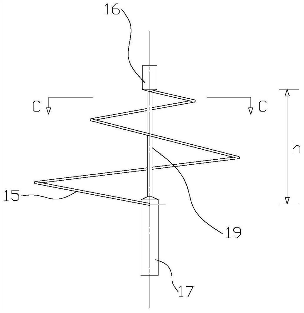
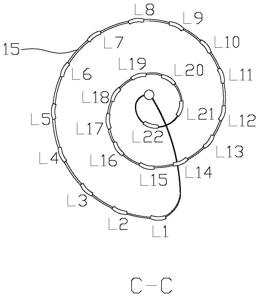
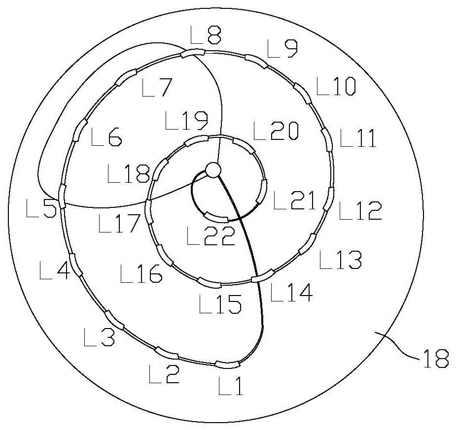
[0032] Such as Figure 1~5 shows a cervical ablation device, including an ablation device and a pulse generator connected thereto, the ablation device includes an ablation tube provided with several electrodes, the body of the ablation tube is a coiled flexible catheter 15, and the flexible The conduit 15 is made of elastic material, and the flexible conduit 15 coils from top to bottom and the radius of the circle formed by the coil gradually expands. The annular small-diameter end is the upper end of the flexible conduit 15, and the large-diameter end is the lower end of the flexible conduit 15. The positive and negative electrodes are arranged alternately along the extension direction of the flexible catheter 15. The total number of positive and negative electrodes is 22, and the number of positive and negative electrodes is the same. The len...


PUM


Abstract

The invention relates to the field of medical apparatus and instruments, in particular to a cervix uterus ablation device. An existing cervix uterus treatment field lacks a pulse electric field ablation device, and existing thermal ablation equipment injures surrounding normal tissues in treatment. The invention provides the cervix uterus ablation device. The cervix uterus ablation device comprises an ablation device and a pulse generator connected with the ablation device, wherein the ablation device comprises an ablation pipe provided with a plurality of electrodes; an ablation pipe body isa coiled flexible guide pipe; the flexible guide pipe is coiled from top to bottom, and an annular radius formed by coiling is gradually increased; an annular small-diameter end is the upper end of the flexible guide pipe, and a big-diameter end is the lower end of the flexible guide pipe; each electrode is subjected to anode and cathode alternant arrangement along a flexible guide pipe extendingdirection; and a guide wire which penetrates in the flexible guide pipe is independently connected with the anode and the cathode and is connected with the pulse generator to supply power. By use of the cervix uterus ablation device disclosed by the invention, non-thermal energy cervix uterus ablation can be realized, and in addition, cervix uterus tissues in an ablation area can be subjected to accurate directional ablation so as to prevent from injuring surrounding normal tissues.

Description

technical field [0001] The invention relates to the field of medical instruments, in particular to a cervical ablation device. Background technique [0002] Cervical cancer has become a public health problem that seriously threatens women's health. Epidemiological studies have found that cervical cancer is currently one of the most common gynecological malignancies, and its incidence rate is second only to breast cancer and colorectal cancer. In recent years, with the popularization of cervical cancer screening, the detection rate of early cervical cancer patients is getting higher and higher, and the age of onset is also showing a younger trend. Radical trachelectomy is considered as the main treatment for early cervical cancer to preserve fertility due to its remarkable short-term and long-term efficacy. For low-risk early-stage cervical cancer patients, more conservative surgical methods such as cervical conization and simple trachelectomy are also safe and feasible. H...

Claims


Application Information

Patent Timeline
IPC IPC(8): A61B18/00
CPCA61B18/00A61B2018/00559A61B2018/00577A61B2018/0072A61B2018/00767
Inventor 陈永刚谢斐胡深张有干陈新华
Owner HANGZHOUREADY BIOLOGICAL TECH CO LTD
Learn More