Primary side feedback constant-current control system

A constant-current control, primary-side feedback technology, applied in the control/regulation system, converting DC power input to DC power output, AC power input converting to DC power output, etc. High cost and other problems, to achieve the effect of reducing power supply development cost, simple control implementation method, and high constant current output accuracy

Active Publication Date: 2021-01-26
NANJING UNIV OF SCI & TECH
View PDF4 Cites 5 Cited by
  • Summary
  • Abstract
  • Description
  • Claims
  • Application Information

AI Technical Summary

Problems solved by technology

In the process of actually adopting this strategy, since the output power Pout of the secondary side is unknown, the input power Pin of the primary side is used to replace the output power Pout of the secondary side, but the calculation of Pin is often too complicated. In addition, to obtain the output power Pout of the secondary side requires An additional sampling circuit is built. The traditional constant current algorithm is too costly to achieve constant current. Because the constant current effect is related to efficiency, the efficiency is greatly affected by the input voltage and load size, but the stability of the current is difficult to achieve high accuracy.
[0005] Since the primary-side feedback cannot directly sample the output current, the open-loop control method based on the primary-side current prediction can realize constant output current control. In order to improve the accuracy of the output current, it is necessary to compensate the current calculation errors introduced by the control delay and related nonlinearities. However, since the primary side constant current control method is based on linear output diode current calculation, it cannot be directly applied to significant nonlinear converters such as active clamping.

Method used


Image

  • Primary side feedback constant-current control system
  • Primary side feedback constant-current control system
  • Primary side feedback constant-current control system

Examples


Embodiment Construction

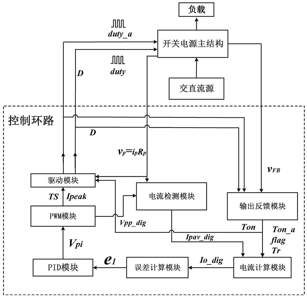
[0041] Such as figure 1 As shown, a primary-side feedback constant current control system includes an output feedback module, a current detection module, a drive module, a current calculation module, an error calculation module, a PID module, and a PWM module. The output feedback module realizes parameter collection and Calculation, the output result is used for the calculation of the current module. The current calculation module performs calculations based on the parameters provided by the output feedback module and the current detection module. The obtained result enters the error calculation module, and compares the obtained result with the reference value. The PID module operation can obtain the peak value of the sampling voltage of the primary side. In the PWM module, the mode can be judged according to the peak value of the sampling voltage, and the next switching cycle Ts and the peak value of the primary side current can be obtained according to the corresponding mode....


PUM


Abstract

The invention discloses a primary side feedback constant current control system, and the system comprises an output feedback module, a current detection module, a driving module, a current calculationmodule, an error calculation module, a PID module and a PWM module, wherein the control system is connected with a controlled switching power supply to form a closed loop; the current detection module and the output feedback module are mainly used for acquiring some basic parameters for realizing a constant-current algorithm, and the current calculation module is used for calculating the currentof a primary side inductor and the excitation inductance current of a transformer in a switch conduction stage. The magnitude of the output current can be obtained by integrating and averaging the output diode current in time, a compensation algorithm is executed on the output value in the digital PID module, the compensation value is output to the PWM control module, and a proper duty ratio is output through the driving module, so the high-precision constant current of the digital power supply is effectively controlled.

Description

technical field [0001] The invention relates to the technical field of isolated converters, in particular to a primary side feedback constant current control system. Background technique [0002] Isolated AC-DC (Alternating Current to Direct Current, referred to as AC-DC) converter can realize electrical isolation between input and output, has the characteristics of safety isolation and high reliability, and is widely used in mobile phones, LED power supplies, notebook computers and other small power applications. By improving the design method of the clamp circuit, the isolated active clamp AC-DC converter realizes the soft switching of the switching tube while recovering the leakage inductance energy of the transformer, which can greatly reduce the switching loss of the converter and improve the conversion efficiency. The switching frequency of the converter can be adjusted to achieve the goal of increasing the power and miniaturization of the converter. [0003] The act...

Claims


Application Information

Patent Timeline
Patent Type & Authority Applications(China)
IPC IPC(8): H02M7/217H02M3/335H02M1/08
CPCH02M7/217H02M7/2176H02M3/33569H02M3/33515H02M3/33523H02M1/08Y02B70/10
Inventor 王冲张翔孙大鹰顾文华
Owner NANJING UNIV OF SCI & TECH
Why Eureka
Try Eureka