Cooling structure of ultrasonic welding head

A cooling structure and ultrasonic technology, which is applied in the field of ultrasonic welding, can solve the problems that the temperature of the welding head is difficult to drop, the heat dissipation effect of the thicker part of the welding head is poor, and the hot air cannot be absorbed and cooled, so as to achieve the effect of easy cooling and good heat dissipation effect

Inactive Publication Date: 2021-01-29
陕西诺盈自动化仪表有限公司
View PDF0 Cites 2 Cited by
  • Summary
  • Abstract
  • Description
  • Claims
  • Application Information

AI Technical Summary

Problems solved by technology

[0004] The purpose of the present invention is to solve the problem that the cooling structure of the ultrasonic welding head in the prior art cannot absorb and cool the hot air near the welding head, the te

Method used


Image

  • Cooling structure of ultrasonic welding head
  • Cooling structure of ultrasonic welding head

Examples


Embodiment 1

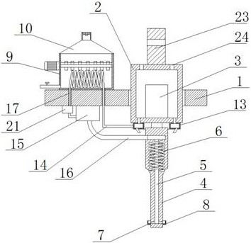
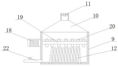
[0021] Example 1 as Figure 1-2 As shown, a cooling structure of an ultrasonic welding head includes a mounting seat 1, an organic casing 2 is installed on the mounting seat 1, a transducer 3 is installed in the casing 2, a welding head 4 is installed at the bottom of the transducer 3, and a welding head 4 is installed on the bottom of the transducer 3. There is a T-shaped gas transmission channel 5 in the head 4, and a spiral heat dissipation channel 6 is opened in the welding head 4. Both ends of the heat dissipation channel 6 are connected with the gas transmission channel 5, and the gas transmission channel 5 is circular and uniform. There are a number of air injection holes 7 at the distance between them. The welding head 4 located below the air injection holes 7 is fixedly sleeved with a diversion cover 8. The upper end of the mounting base 1 is fixedly connected with a cooling box 9, and the upper opening of the cooling box 9 is connected to a row. Gas hood 10, exhaust ...

Embodiment 2

[0022] Embodiment 2 is on the basis of embodiment 1 such as Figure 1-2 As shown, a motor 18 is installed on the wall of the cooling box 9, and the output end of the motor 18 is connected with a rotating rod 19 through a coupling. Several rotating plates 20 are fixedly connected to the wall of the rotating rod 19. When the welding head 4 is cooling, the motor 18 is started to drive the rotating rod 19 and the rotating plate 20 to rotate, so that the rotating plate 20 beats the liquid surface of the cooling liquid to speed up cooling. The cooling speed of the liquid is improved, and the use time of the cooling liquid is prolonged.

Embodiment 3

[0023] Embodiment 3 is such as on the basis of embodiment 1 figure 1 As shown, a drying box 21 is connected to the wall of the gas outlet pipe 17, and the drying box 21 is fixedly connected to the bottom of the mounting base 1. The drying box 21 is filled with a desiccant, which can dry the gas passing through the bellows 12.


PUM


Abstract

The invention relates to the technical field of ultrasonic welding, and discloses a cooling structure of an ultrasonic welding head. The cooling structure comprises a mounting base, wherein a machineshell is mounted on the mounting base, an energy converter is mounted in the machine shell, the welding head is mounted at the bottom of the energy converter, a T-shaped air conveying channel is formed in the welding head, and a spiral heat dissipation channel is formed in the welding head; the two ends of the heat dissipation channel are communicated with the air conveying channel, a plurality ofair spraying holes are annularly, evenly and equidistantly formed in the air conveying channel, the welding head located below the air spraying holes is fixedly sleeved with a flow guide cover, the upper end of the mounting base is fixedly connected with a cooling box, and an opening in the upper end of the cooling box is communicated with an exhaust hood; and an exhaust fan is mounted in the output end of the exhaust hood. According to the cooling structure, hot air near the welding head can be sucked and cooled, so that the temperature of the welding head can be rapidly decreased, the heatdissipation effect on the thick part of the welding head is better, and the welding head can be comprehensively cooled conveniently.

Description

technical field [0001] The invention relates to the technical field of ultrasonic welding, in particular to a cooling structure of an ultrasonic welding head. Background technique [0002] Ultrasonic welding is usually used for plastic welding. It completely replaces the traditional industry of glue bonding. In the process of ultrasonic welding, there are no bolts, nails, buckles, welding materials or adhesives. The adhesive or viscose water is faster, and the drying time is also very fast, the welding process can be easily automated, and can be easily customized to suit the specific specifications of various types of products being welded. Due to the high frequency and high energy of ultrasonic waves, it will produce significant thermal effects, so it is necessary to do cooling treatment at the ultrasonic welding head. [0003] The cooling structure of the existing ultrasonic welding head cannot absorb and cool the hot air near the welding head, the temperature on the weld...

Claims


Application Information

Patent Timeline
IPC IPC(8): B29C65/08B29C35/16
CPCB29C35/16B29C65/08B29C2035/1658
Inventor 李军荣
Owner 陕西诺盈自动化仪表有限公司
Why Eureka
Try Eureka