Acoustic emission measurement method for particle parameters in gas-solid system

An internal particle and acoustic emission technology, which is applied in the direction of material analysis, measurement device, and particle suspension analysis using acoustic wave emission technology, can solve the problems of inability to realize local particle parameter detection, inability to obtain spatial distribution information, singleness, etc., and achieve anti- Strong interference ability, strong compatibility, and flexible coupling effect

Active Publication Date: 2021-01-29
ZHEJIANG UNIV
View PDF9 Cites 2 Cited by
  • Summary
  • Abstract
  • Description
  • Claims
  • Application Information

AI Technical Summary

Problems solved by technology

However, the current invasive acoustic emission detection application system is single (dilute-phase pneumatic conveying), and more importantly, the acoustic emission signal measured by the traditional probe includes both the information at the end point of the probe and the The information that extends into other p

Method used


Image

  • Acoustic emission measurement method for particle parameters in gas-solid system
  • Acoustic emission measurement method for particle parameters in gas-solid system
  • Acoustic emission measurement method for particle parameters in gas-solid system

Examples


Embodiment 1

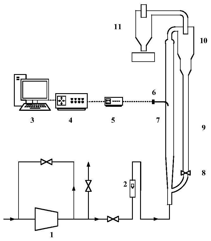
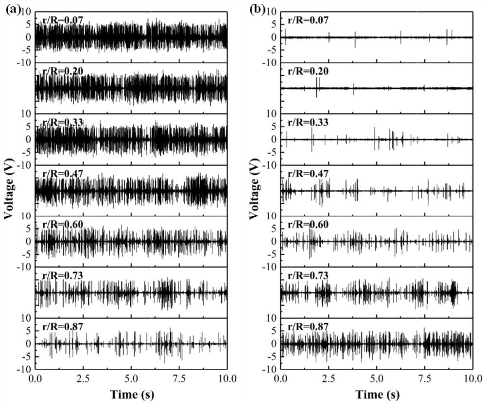
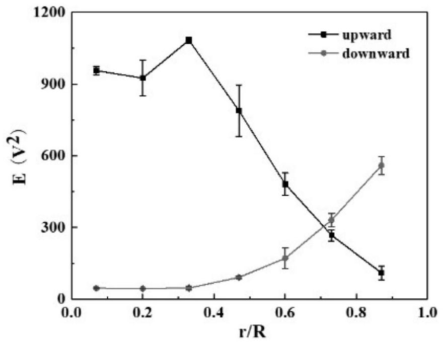
[0039]The shielded curved probe is used to measure the acoustic emission signals at different radial positions in the riser, and the acoustic emission signals in two different directions are collected at the same position. When the guiding wave surface is facing downwards, the acoustic wave signal generated by the action of upward moving particles and the guiding wave surface is collected; when the guiding wave is facing upward, the acoustic wave signal generated by the action of downward moving particles and the guiding wave surface is collected.figure 2 Shown are the time-domain diagrams of acoustic emission signals generated by particles moving up and down at different radial positions in the riser. The original signal shows that there are particles moving upward and downward at different radial positions in the riser. In order to further characterize the movement direction of the particle body, the energy of the acoustic emission signal at different radial positions is calculate...

Embodiment 2

[0041]Figure 4 Shown is a schematic diagram of a single particle experimental device. The air enters the buffer tank after being pressurized by the air compressor, and is controlled by the solenoid valve to generate a pulsed air flow. The polypropylene particles with the same particle size as the riser are selected and filled into the bore at the right end of the solenoid valve. During the experiment, the particles accelerated by the pulsed airflow collide with the wave surface of the probe to generate acoustic emission signals, and the collision speed is obtained by shooting with a high-speed camera. By adjusting the air pressure in the buffer tank, single-particle experiments can be performed under different particle velocity conditions. The acoustic emission signal energy or the acoustic emission signal peak value is extracted as the characteristic value, and the particle velocity model is established through the neural network algorithm. Extract the acoustic emission signal ener...

Embodiment 3

[0043]Using double-core shielded probes and fusion of acoustic emission sensor arrays, the time difference (delay time) of particles passing through adjacent probes is obtained through cross-correlation calculation, and the ratio of the distance between adjacent probes and the signal time difference is calculated to obtain local particles speed.

[0044]

[0045]Among them, v is the particle velocity; L is the effective distance between adjacent probes; τ is the delay time calculated from the cross-correlation of acoustic emission signals at adjacent positions.


PUM


Abstract

The invention discloses an acoustic emission measurement method for particle parameters in a gas-solid system. The acoustic emission measurement method comprises the following steps: acquiring an acoustic emission signal generated when particles at any position in the gas-solid system impact a shielding type wave guide rod by utilizing the shielding type wave guide rod and a sensor; analyzing thereceived acoustic emission signal, and selecting time domain, frequency domain and state space parameters as characteristic values; and carrying out correlation modeling on the acoustic emission signal characteristic value and particle parameters in the gas-solid system to realize acoustic emission detection of the particle parameters. The defect that traditional acoustic emission detection can only be used for space average parameter detection is overcome, and measurement of the local particle movement direction, the local particle speed, the local particle concentration and the local particle flux in a gas-solid system and measurement of the particle flow pattern in the gas-solid system are achieved.

Description

Technical field[0001]The invention belongs to the field of multiphase flow information detection, and specifically relates to an acoustic emission measurement method for particle parameters in a gas-solid system.Background technique[0002]Multiphase flow exists widely in many fields, such as chemical industry, petroleum, power and so on. In the gas-solid system, the particle flow characteristics are complex, and the flow parameters are difficult to accurately measure. The existing detection methods of particle parameters in gas-solid systems include particle tracing technology, electrical capacitance tomography technology, electrostatic detection technology, etc., but due to their respective limitations such as strong intrusiveness, complex systems, and high prices, they are difficult to use To the actual industrial environment.[0003]In recent years, some scholars have tried to use the acoustic emission detection system coupled with probes to obtain internal information of the gas-so...

Claims


Application Information

Patent Timeline
IPC IPC(8): G01N15/00G01N15/06G01N29/14G01N29/22
CPCG01N15/00G01N15/06G01N29/14G01N29/222G01N2015/0003
Inventor 黄正梁盛涛杨遥张鹏孙婧元蒋斌波廖祖维阳永荣
Owner ZHEJIANG UNIV
Why Eureka
Try Eureka