Magnetotelluric denoising method and system

A magnetotelluric and magnetotelluric sounding technology, applied in the field of data processing, can solve the problems of increased processing time, over-processing of effective signals, and inability to effectively remove large-scale noise and mutation noise.

Active Publication Date: 2021-01-29
JILIN UNIV
View PDF5 Cites 2 Cited by
  • Summary
  • Abstract
  • Description
  • Claims
  • Application Information

AI Technical Summary

Problems solved by technology

[0003] At present, the removal methods for magnetotelluric noise can be mainly divided into the following three categories: ①Time-domain processing method: this type of method mainly identifies and removes the obvious noise form in the time series, and its typical representatives include morphological filtering method, subspace Enhancement algorithm, matching pursuit and compressed sensing and other methods, this type of algorithm has a good processing effect on noise of a specific shape, but the suppression effect on complex shape noise is not ideal
For example, the morphological filtering method using rectangular structural elements only has the best processing effect on square waves, but cannot effectively remove large-scale noise and sudden noise of other forms such as charge and discharge triangular waves.
Therefore, at present, multiple time-domain methods are often combined for denoising processing, but the corresponding processing time also increases; ②Time-frequency conversion method: convert the time series to other domains (such as frequency domain, wavelet domain, etc.), The spectral information of the signal is used to remove noise. Typical repre...

Method used


Image

  • Magnetotelluric denoising method and system
  • Magnetotelluric denoising method and system
  • Magnetotelluric denoising method and system

Examples


Embodiment Construction

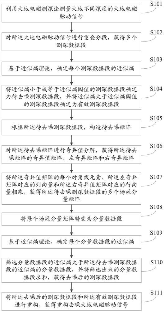
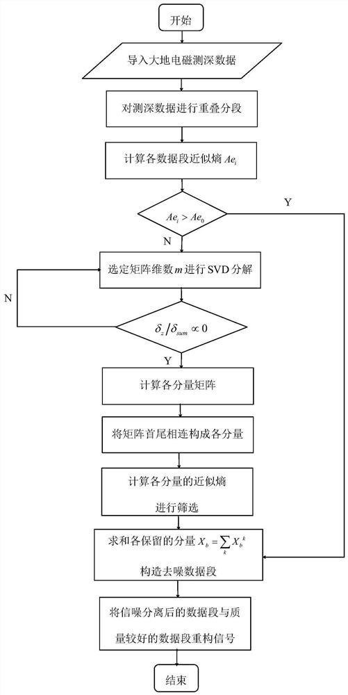
[0079] The following will clearly and completely describe the technical solutions in the embodiments of the present invention with reference to the accompanying drawings in the embodiments of the present invention. Obviously, the described embodiments are only some, not all, embodiments of the present invention. Based on the embodiments of the present invention, all other embodiments obtained by persons of ordinary skill in the art without making creative efforts belong to the protection scope of the present invention.

[0080] The object of the present invention is to provide a magnetotelluric denoising method and system to reduce over-processing of data and improve the accuracy of data denoising.

[0081] In order to make the above objects, features and advantages of the present invention more comprehensible, the present invention will be further described in detail below in conjunction with the accompanying drawings and specific embodiments.

[0082] In order to reduce the ...


PUM


Abstract

The invention relates to a magnetotelluric denoising method and system. The method comprises the steps of carrying out the overlapping segmentation of a magnetotelluric pulsation signal, determining the approximate entropy of each sounding data segment, determining the sounding data segment with the approximate entropy greater than an approximate entropy threshold as an effective sounding data segment, and determining other sounding data segments as to-be-denoised sounding data segments; selecting approximate entropy to screen the data segments, so that 'over-processing' of the effective sounding data segments is prevented; performing singular value decomposition on the to-be-denoised sounding data segments, multiplying the decomposed singular value matrix, the left singular matrix and theright singular matrix to obtain a plurality of component matrixes, constructing corresponding component data segments, determining the approximate entropy of each component data segment, and summingthe screened component data segments of which the approximate entropy is greater than the approximate entropy of the sounding data segments; obtaining denoised sounding data segments, and achieving the purpose of denoising; and finally, reconstructing the denoised sounding data segments and the effective sounding data segments to obtain a reconstructed denoised magnetotelluric pulsation signal, thereby improving the accuracy of data denoising.

Description

technical field [0001] The invention relates to the field of data processing, in particular to a magnetotelluric denoising method and system. Background technique [0002] Magnetotelluric sounding (MT for short) observes the component disturbance value of the natural electromagnetic field signal through the underground medium on the surface to obtain the electrical structure of the underground medium. Its field source is a natural electromagnetic field, and the effective signal originates from the interaction of lightning discharge, solar wind and the earth's magnetosphere. Compared with the electromagnetic sounding method of artificial field source, MT has the advantages of rich frequency band information and large detection depth, so it is widely used It is used in many fields such as oil and gas field census and exploration, earthquake prediction, ore prospecting. However, the natural electromagnetic field signal is weak, and it is susceptible to interference from variou...

Claims


Application Information

Patent Timeline
IPC IPC(8): G01V3/38
CPCG01V3/38
Inventor 韩江涛周瑞刘立家郭振宇
Owner JILIN UNIV
Why Eureka
Try Eureka