Suspension type medium-low speed permanent magnet suspension train motion control system and control method

A technology of maglev train and control system, applied in control system, vector control system, linear motor control and other directions, can solve the problems of fuzzy PID control unable to achieve the expected effect, system lag, etc. The effect of high efficiency and modularity

Active Publication Date: 2021-01-29
江西理工科技产业有限公司
View PDF5 Cites 0 Cited by
  • Summary
  • Abstract
  • Description
  • Claims
  • Application Information

AI Technical Summary

Problems solved by technology

However, in the actual application process, due to the linear motor drive itself, there is a certain hysteresis in the system, and the fuzzy PID control cannot achieve the expected effect in suppressing the hysteresis.

Method used


Image

  • Suspension type medium-low speed permanent magnet suspension train motion control system and control method
  • Suspension type medium-low speed permanent magnet suspension train motion control system and control method
  • Suspension type medium-low speed permanent magnet suspension train motion control system and control method

Examples


Embodiment 1

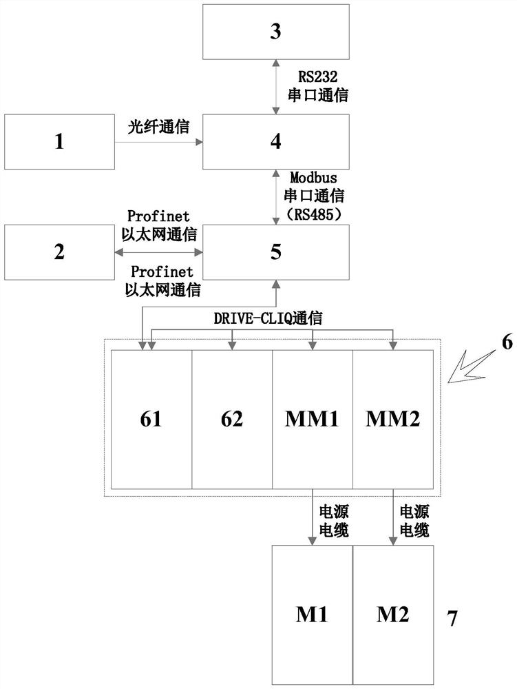
[0040] A motion control system for suspended medium and low-speed permanent maglev trains, such as figure 1 As shown, including host computer module, control unit module, motion control module and cross loop system 1;

[0041] Described upper computer module comprises KPT700 model touch screen 2 and IPC-610 main control computer 3; Described control unit module comprises control module 4 and PLC controller 5, and control module 4 adopts STM32F407 microcontroller, and PLC controller 5 selects Siemens S7 for use -1200 PLC; the motion control module includes a book-type S120 frequency converter 6, a permanent magnet linear synchronous motor 7 with a long stator without an iron core (two permanent magnet linear synchronous motors M1 and M2 are included in this embodiment);

[0042] The cross loop system 1 is communicatively connected to the control module 4 through an optical fiber interface, and is used to transmit the current position and speed information of the train to the co...

Embodiment 2

[0058] This embodiment provides a method for controlling a permanent maglev train using the control system described in Embodiment 1. In this embodiment, the permanent maglev train runs on the suspended permanent maglev test line between site one and site two, and the length of the suspended permanent maglev test line is X meters. Among them, QW78 means MM1 control word; QW102 means MM2 control word; QW80 means MM1 speed given; QW104 means MM2 speed given.

[0059] Such as Figure 5 As shown, the specific process is as follows:

[0060] 7) Once the permanent maglev train is parked at the station and ready to depart, the main control computer sends out dispatch command information, which includes target speed, target parking position and train start signal.

[0061] 8) The PLC controller receives the starting command information, controls the contactor KM1 and KM2 contacts to pull and sends a message control word to the S120 inverter: QW78=16#47F (motor start), target speed w...


PUM


Abstract

The invention discloses a suspension type medium-low speed permanent magnet suspension train motion control system and a control method, which adopt a long stator permanent magnet synchronous linear motor mode to drive a medium-low speed permanent magnet suspension train, so that the train has stronger climbing ability, is lighter and more convenient and has higher operation efficiency. An STM32F407 control module and a Siemens S7-1200 PLC are selected as a dual-core controller, an S120 frequency converter is selected as a motor driving device, the modularization degree is high, the structureis simple, the stability is good, the engineering cost is low, and maintenance is convenient. Besides, a cross loop positioning mode is selected to feed back the position and speed information of thepermanent magnet suspension train, the positioning precision is good, and a rotor flux linkage directional decoupling control mode that the d-axis component of stator current is constant to be zero isadopted to construct a position, speed and current three-closed-loop vector control system.

Description

technical field [0001] The invention relates to the technical field of maglev train control, in particular to a motion control system and control method for a suspended medium-low speed permanent maglev train. Background technique [0002] At present, at home and abroad, the optimal choice for the traction mode of medium and low-speed maglev trains is to use short-stator asynchronous linear motors for traction. The short stator asynchronous linear motor traction method is to install a complete set of traction devices such as three-phase armature windings, traction transformers and converters on the vehicle, and install induction rails on the track as the rotor. The vehicle generally uses the method of contacting and receiving current from the ground power supply system. Power supply. The structural advantages of this method are simple structure, easy maintenance, and low cost, but the main disadvantages are low power, low efficiency, and heavy train body. my country's Chan...

Claims


Application Information

Patent Timeline
IPC IPC(8): H02P21/00H02P25/064H02P6/00B60L13/04
CPCH02P21/001H02P25/064H02P6/006B60L13/04Y02T90/16
Inventor 过振宇樊宽刚刘鸿恩韩树人
Owner 江西理工科技产业有限公司
Why Eureka
Try Eureka