
A multi-level photovoltaic power generation system topology and its control method

A photovoltaic power generation system and topology technology, applied in the field of multi-level photovoltaic power generation system topology and its control, can solve the problems of network paralysis, inconvenient installation, and inflexibility, etc., achieve maintenance stability, improve convenience, increase The effect of flexibility

Active Publication Date: 2022-01-14
NAVAL UNIV OF ENG PLA
View PDF2 Cites 0 Cited by
  • Summary
  • Abstract
  • Description
  • Claims
  • Application Information

AI Technical Summary

Problems solved by technology

[0004] Aiming at the deficiencies of the existing technology, the present invention provides a multi-level photovoltaic power generation system topology and its control method, which solves the problem that the overall installation structure of the existing photovoltaic power generation system in the above background technology is relatively single during use. It is not flexible enough, which leads to inconvenient installation. In addition, the network terminal connected to the photovoltaic power generation system has a single topology structure, which has obvious disadvantages and easily causes network paralysis.

Method used


Image

  • A multi-level photovoltaic power generation system topology and its control method
  • A multi-level photovoltaic power generation system topology and its control method
  • A multi-level photovoltaic power generation system topology and its control method

Examples


Embodiment Construction

[0032] The following will clearly and completely describe the technical solutions in the embodiments of the present invention with reference to the accompanying drawings in the embodiments of the present invention. Obviously, the described embodiments are only some, not all, embodiments of the present invention.

[0033] In the description of the present invention, unless otherwise stated, the meaning of "plurality" is two or more; the terms "upper", "lower", "left", "right", "inner", "outer" , "front end", "rear end", "head", "tail", etc. indicate the orientation or positional relationship based on the orientation or positional relationship shown in the drawings, and are only for the convenience of describing the present invention and simplifying the description, rather than Nothing indicating or implying that a referenced device or element must have a particular orientation, be constructed, and operate in a particular orientation should therefore not be construed as limiting ...


PUM


Abstract

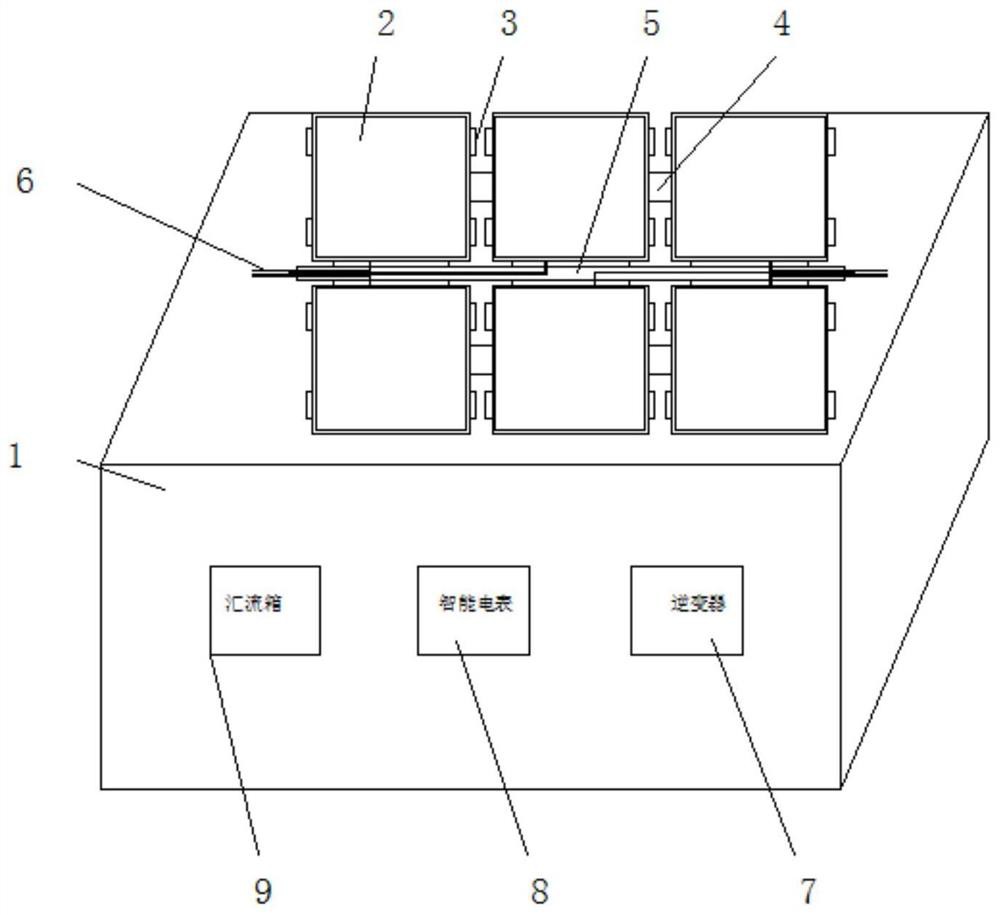
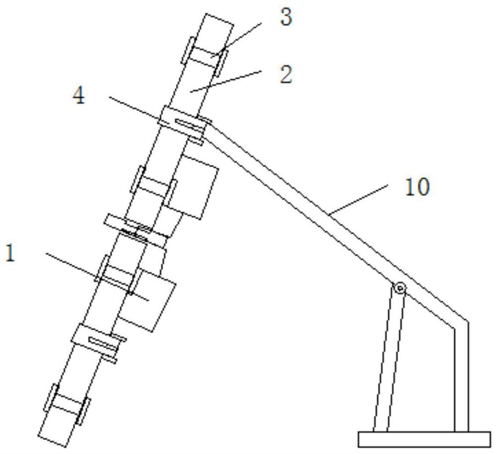
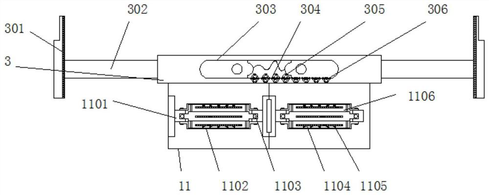
The invention discloses a multi-level photovoltaic power generation system topology and its control method, relates to the technical field of photovoltaic power generation systems, specifically a multi-level photovoltaic power generation system topology and its control method, including a power generation system box and a support rod , the top of the power generation system box is equipped with a solar array panel, and the upper and lower surfaces of the rear side of the solar array panel are provided with clamp seats, the middle of the rear side of the solar array panel is equipped with a bottom rod, and the middle of the solar array panel A cable trough is placed, and an inverter, a smart meter and a combiner box are placed inside the power generation system box, and the support bar is located at the rear side of the bottom bar. The topological structure of the multi-level photovoltaic power generation system is provided with a clamping seat, which can clamp the solar array panel to avoid damage to the edge of the solar array panel. At the same time, the setting of the clamping seat facilitates the installation of the battery installation box , which is conducive to the connection between the battery pack and the solar array panel.

Description

technical field [0001] The invention relates to the technical field of photovoltaic power generation systems, in particular to a multi-level photovoltaic power generation system topology and a control method thereof. Background technique [0002] Photovoltaic power generation system is now the main source of power generation. Its technology is mainly derived from solar energy. By using the sun's irradiation, it converts sunlight into solar energy, and then converts it into electrical energy through the conversion of electrical energy, and supplies it to the national grid and household grid. Now, most of the photovoltaic power generation systems use multi-level, so that the energy is sufficient and the advantages are great. When solar energy is integrated into the grid, it will be connected to the network end, and the connection between the network ends will ensure that the entire network of normal operation. [0003] During the use of the existing photovoltaic power generat...

Claims


Application Information

Patent Timeline
Patent Type & Authority Patents(China)
IPC IPC(8): H02S10/00H02S10/20H02S20/00H02S20/30H02S50/00H02S40/30H02J3/38H02J7/35
CPCH02S10/00H02S10/20H02S20/00H02S20/30H02S50/00H02S40/30H02J3/381H02J7/35H02J2300/24Y02E10/56Y02E70/30
Inventor 高键鑫杨刚赵镜红武晓康汪小娜
Owner NAVAL UNIV OF ENG PLA
Learn More