Testing platform for performance of shoulder joint prosthesis
A test platform and technology of shoulder joints, applied in the direction of shoulder joints, prostheses, joint implants, etc., can solve the problems of implant wear, failure, short-term and long-term failure of artificial shoulder joints that cannot be predicted and effectively evaluated, etc. problems, to achieve the effect of simple operation, reduced labor intensity and high degree of automation
- Summary
- Abstract
- Description
- Claims
- Application Information
AI Technical Summary
Problems solved by technology
Method used
Image
Examples
Embodiment 1
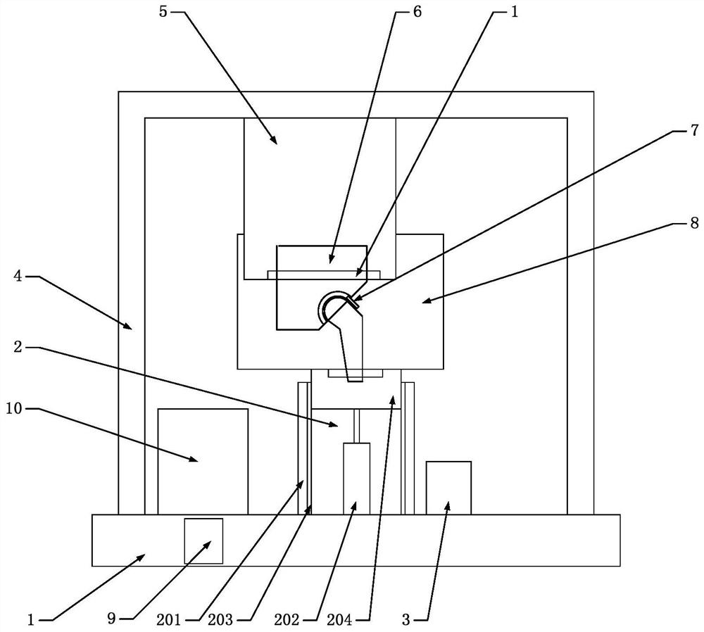
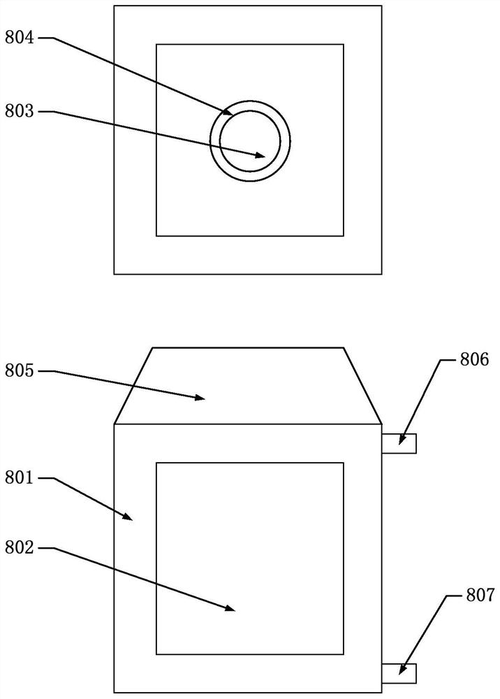
[0024] A shoulder joint prosthesis performance testing platform, such as figure 1 As shown, the shoulder joint prosthesis performance testing platform includes: a testing platform 1, a humeral head fixing platform 2, an air pump 3, a complete machine support 4, a parallel rotating platform 5, a glenoid socket fixing platform 6, a pressure sensor 7, and a simulation chamber 8 , PLC 9, PC upper computer 10. The humeral head fixing platform, the air pump and the whole machine bracket are fixed on the test platform, the parallel rotating platform is fixed on the whole machine bracket, the glenoid fossa fixing platform is fixed on the moving platform of the parallel rotating platform, the The simulation chamber is located on the upper end of the humeral head fixation platform, and is used to simulate the real human body friction conditions when the shoulder joint prosthesis moves. The pressure sensor is set on the artificial shoulder joint prosthesis to be tested, and is used to co...
Embodiment 2
[0031] A shoulder joint prosthesis performance testing platform, its overall structure is as follows: Figure 4 As shown, the PLC is respectively connected with the PC upper computer, the servo motor M1, the servo motor M2, the servo motor M3, the air cylinder, the air pump, and the pressure sensor. The PLC is electrically connected to the PC host computer to set functional parameters such as test type, number of cycles, applied load, and motion curve; the PLC is electrically connected to the servo motor M1, servo motor M2, and servo motor M3 to drive the corresponding Rotating pairs R11, R21, and P3 operate in parallel to control the rotation and speed of the parallel rotating platform; the PLC is electrically connected to the cylinder and the air pump to control the height position and the applied load of the humeral head fixed platform; the PLC and The pressure sensor is electrically connected and used to feed back the load on the artificial shoulder joint prosthesis to for...
Embodiment 3
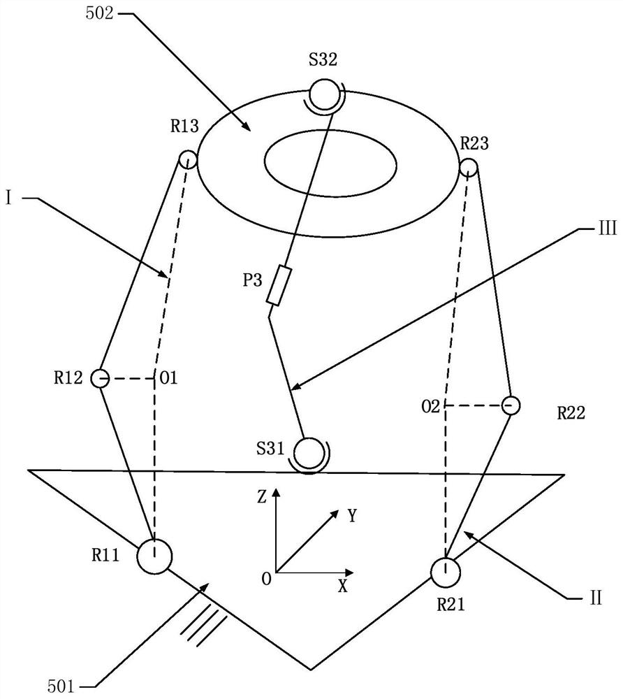
[0033] Such as figure 2 As shown, the parallel mechanism of the parallel rotating platform has a total of m=9 motion pairs and n=8 components. According to the degree of freedom (DOF) formula
[0034]
[0035]
[0036] Determine that the degree of freedom (DOF) of the mechanism is F=3, and the three degrees of freedom are respectively rotations along the X axis, the Y axis and the Z axis;
[0037]For a mechanism with a degree of freedom F, preselect F kinematic pairs as driving pairs and stiffen them. If the obtained new mechanism degree of freedom F’=0, then the preselected F kinematic pairs can be driving pairs at the same time. Since the degree of freedom of the mechanism is 3, the revolving pairs R11, R21, and P3 of the three branches are preselected as the driving pair, and they are stiffened to obtain the degree of freedom of the stiffened mechanism F'=0, which meets the existence criterion of the driving pair.
PUM
 Abstract
Description
Claims
Application Information
 - R&D
- Intellectual Property
- Life Sciences
- Materials
- Tech Scout
- Unparalleled Data Quality
- Higher Quality Content
- 60% Fewer Hallucinations
Browse by: Latest US Patents, China's latest patents, Technical Efficacy Thesaurus, Application Domain, Technology Topic, Popular Technical Reports.
© 2025 PatSnap. All rights reserved.Legal|Privacy policy|Modern Slavery Act Transparency Statement|Sitemap|About US| Contact US: help@patsnap.com


