Injection molding equipment for hollow pipe fitting

A technology for injection molding equipment and hollow pipe fittings, which is applied in the field of injection molding equipment for hollow pipe fittings, can solve problems such as the surface finish of products that cannot guarantee material flow compactness, and achieve the effect of ensuring the overall compactness of products, ensuring product quality, and reducing equipment failure rates.

Active Publication Date: 2021-02-02
扬州吉山津田光电科技有限公司
View PDF7 Cites 0 Cited by
  • Summary
  • Abstract
  • Description
  • Claims
  • Application Information

AI Technical Summary

Problems solved by technology

Although the injection molding machine in this application improves the production efficiency, it cannot guarantee the compactness of the material flow and the smoothness of the product surface during the injection molding production process, which needs to be improved

Method used


Image

  • Injection molding equipment for hollow pipe fitting
  • Injection molding equipment for hollow pipe fitting
  • Injection molding equipment for hollow pipe fitting

Examples


Embodiment 1

[0053] The injection molding equipment of the hollow pipe fitting of the present embodiment, the device comprises:

[0054] Injection molding machine 1000, the material flow for injection molding hollow pipe fittings;

[0055] Cooling and shaping unit 2000, which is arranged on the side of the product outlet of the injection molding machine 1000, to cool and shape the injection molding product;

[0056] Traction unit 3000, which is arranged on one side of the cooling and shaping unit 2000, and pulls the injection molded product for cooling and shaping;

[0057] A cutting unit 4000, which is arranged on one side of the traction unit 3000, cuts the injection molded product into a specified length;

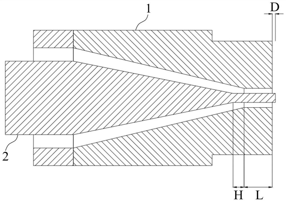
[0058] The injection molding machine 1000 is provided with an injection mold 100 for forming a hollow pipe, and the injection mold 100 includes:

[0059] Die cover 1, which is hollow columnar;

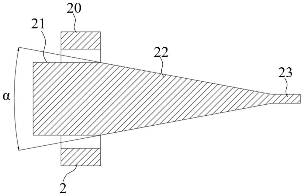
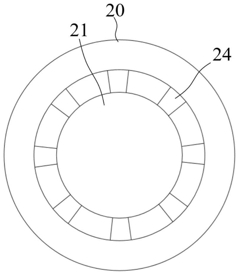
[0060] Cone angle hole section 10, which is opened in the middle of one end face of di...

Embodiment 2

[0070] The injection molding equipment for hollow pipe fittings of this embodiment is further improved on the basis of Embodiment 1. The cutting unit 4000 is slidably connected to the slideway 4001, and the length direction of the slideway 4001 is set parallel to the moving direction of the injection molded product. At this time, the cutting unit 4000 moves along the length direction of the slideway 4001 through the driving member, and the moving speed is the same as that of the injection molded product.

[0071] Since the injection molding machine 1000 is in uninterrupted production, the injection molded product is constantly moving under the traction of the traction unit 3000, and the cutting action of the cutting unit 4000 is perpendicular to the moving direction of the injection molded product. During the period from the product to the completion of cutting, the injection molded product cannot be moved, which will inevitably affect the action of the traction unit 3000 and t...

Embodiment 3

[0073] The injection molding equipment for hollow pipes in this embodiment is further improved on the basis of Embodiment 2. The core segment 23 of the mold core 2 protrudes from the mold sleeve 1 at a distance D, and 1mm≤D≤2mm.

[0074] like figure 1 As shown, the core section 23 protrudes out of the mold sleeve 1 to a suitable length, which can play a certain guiding role for the hollow pipe fittings produced by molding, and can also effectively prevent the hollow part from closing and deforming after the pipe fittings protrude. However, the core section 23 The distance D extending out of the mold sleeve 1 is too long, which will cause the inner wall to shrink during the extrusion process of the hollow pipe fittings, which will affect the product quality. If D is too short, it will not play its due role. 1mm≤D≤2mm, the best effect.


PUM


Abstract

The invention discloses injection molding equipment for a hollow pipe fitting, and belongs to the field of injection molding equipment. The injection molding equipment comprises an injection molding machine, a cooling and shaping unit, a traction unit and a cutting unit, wherein an injection mold is arranged on the injection molding machine, and comprises a mold sleeve, a taper angle hole section,a diameter bearing hole section and a mold core; the taper angle hole section is formed in the middle of one end surface of the mold sleeve in the central axis direction of the mold sleeve; the diameter bearing hole section is formed in the middle of the other end surface of the mold sleeve in the central axis direction of the mold sleeve, and communicates with the taper angle hole section; the mold core is connected with the mold sleeve, and comprises a taper section and a mold core section; the taper section is arranged in the taper angle hole section; and one end of the mold core section is connected with the taper section, and the other end of the mold core section penetrates through the diameter bearing hole section and extends out of the mold sleeve. The injection mold on the injection molding machine can quickly mold the hollow pipe fitting with uniform density and smooth surface, and can accurately guide injection molding products to enter the cooling and shaping unit for molding; the traction unit prevents the injection molding products from being accumulated; and finally, by the cutting unit, the required length of the hollow pipe fitting is obtained. The injection molding equipment has the characteristics of high production efficiency and high product quality.

Description

technical field [0001] The invention belongs to the technical field of injection molding equipment, and more specifically relates to an injection molding equipment for hollow pipes. Background technique [0002] Injection molding is a method of producing industrial products. The thermoplastic material flow is formed into the required shape by using different molding molds through the injection molding machine. [0003] When the existing injection molding equipment produces hollow pipe fittings, the product quality level is uneven, there are defects such as uneven density distribution of pipe fittings, and rough pipe wall surface. [0004] After searching, the Chinese patent publication number: CN 110696320 A; publication date: January 17, 2020; discloses a PVC pipe fitting injection molding machine, including a base, a driving device is installed on the base, and an inlet is installed above the base. A material device, a controller is installed on the base, an injection mol...

Claims


Application Information

Patent Timeline
Patent Type & Authority Applications(China)
IPC IPC(8): B29C48/09B29C48/32B29C48/00B29L23/00
CPCB29C48/09B29C48/32B29C48/0022B29L2023/22Y02P70/10
Inventor 李同裕
Owner 扬州吉山津田光电科技有限公司
Why Eureka
Try Eureka