Device for slowing down blockage of ammonia spraying pipeline adjusting door and using method

A pipeline and screw plug technology is applied in the field of devices for slowing down the clogging of the adjustment door of the ammonia injection pipeline.

Inactive Publication Date: 2021-02-05
SDIC BEIBUWAN ELECTRIC POWER CO LTD
View PDF4 Cites 0 Cited by
  • Summary
  • Abstract
  • Description
  • Claims
  • Application Information

AI Technical Summary

Problems solved by technology

[0002] At present, the preparation method of synthetic ammonia is mainly to make raw materials such as coal and natural gas into crude raw material gas containing hydrogen and nitrogen, and to purify the crude raw material gas. It is very likely that the gas purification is not complete during the production of synthetic ammonia, and the synthetic catalytic catalyst falls off, causing compressor oil, catalyst catalyst, rust, water and other impurities to be suspended in the liquid ammonia, and they enter the evaporator coil together with the liquid ammonia. , the liquid ammonia is vaporized and precipitated
[0003] Today, in order to respond to environmental protection policies to reduce nitrogen oxide emissions, liquid ammonia is used as a denitrification agent in the existing technology. Due to factors such as the quality of liquid ammonia and the material of the pipeline, there are some black viscous reaction residues in the ammonia gas pipeline. It often leads to blockage of the liquid ammonia adjustment door. In severe cases, the ammonia system needs to be shut down to isolate and clear the blockage, which seriously affects the normal operation of the ammonia injection system.

Method used


Image

  • Device for slowing down blockage of ammonia spraying pipeline adjusting door and using method
  • Device for slowing down blockage of ammonia spraying pipeline adjusting door and using method

Examples


Embodiment Construction

[0022] The following will clearly and completely describe the technical solutions in the embodiments of the present invention with reference to the accompanying drawings in the embodiments of the present invention. Obviously, the described embodiments are only some, not all, embodiments of the present invention.

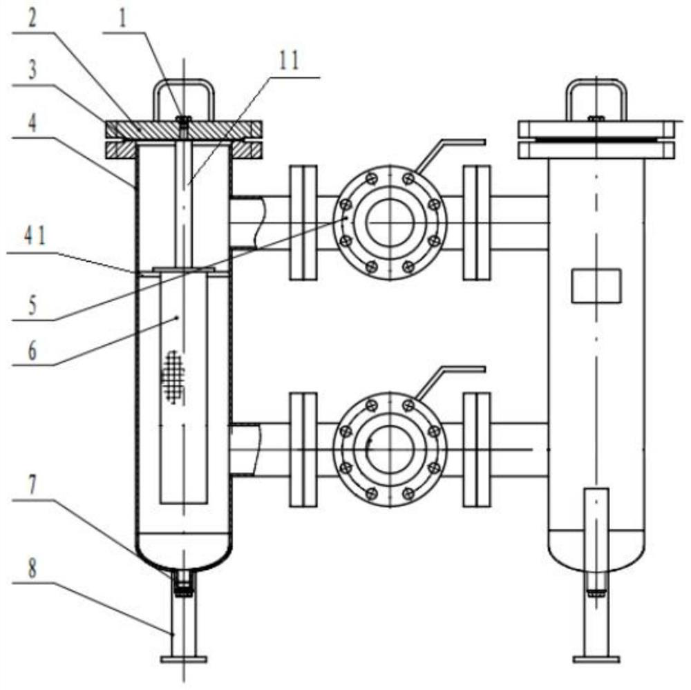
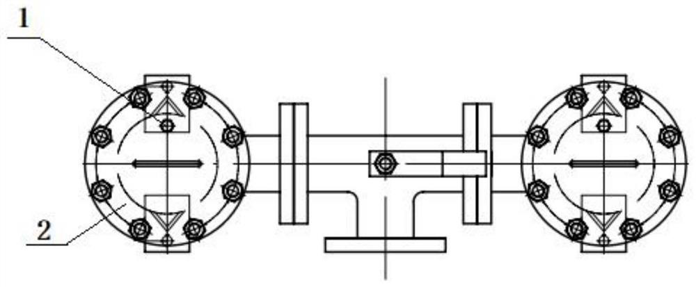
[0023] refer to Figure 1-2 , a device for slowing down the clogging of the adjustment door of the ammonia injection pipeline, comprising a filter housing 4, an inlet triangle valve 5, an outlet triangle valve 9, a filter element 6, legs 8 and an upper end cover 2;

[0024] Two of the filter housings 4 form a group and are connected together; two upper and lower connecting pipes are arranged between the two filter housings 4; the inlet triangle valve 5 and the outlet triangle valve 9 are respectively installed on two on a connecting pipe;

[0025] The inlet triangle valve 5 and the outlet triangle valve 9 serve as a connecting bridge between the two filters,

[002...


PUM


Abstract

The invention relates to the field of ammonia spraying pipeline assistance, in particular to a device for slowing down blockage of an ammonia spraying pipeline adjusting door and a using method. The device comprises filter shells, inlet triangular valves, outlet triangular valves, a filter element, supporting legs and upper end covers; every two filter shells form a group and are connected in a matched mode; an upper connecting pipe and a lower connecting pipe are arranged between the two filter shells of each group; the inlet triangular valves and the outlet triangular valves are respectivelymounted on the two connecting pipes in groups; and the upper end covers cover the tops of the filter shells, and sealing rubber pads are further arranged at the joints of the upper end covers and thefilter shells. In the embodiment of the invention, the layout of the filter is optimized, and the filter element and the double-valve design for gas circuit switching are additionally arranged, so that the filter can intercept and filter most residual impurities, and the phenomenon of blockage of an ammonia injection adjusting door is avoided; impurities can be filtered out through the filter, and a filter element of the filter is periodically cleaned; and in the overhaul and maintenance process of the device, only gas supply management needs to be switched, and outage and standby are not needed.

Description

technical field [0001] The invention relates to the auxiliary field of ammonia injection pipelines, in particular to a device and method for slowing down the clogging of an ammonia injection pipeline adjustment door. Background technique [0002] At present, the preparation method of synthetic ammonia is mainly to make raw materials such as coal and natural gas into crude raw material gas containing hydrogen and nitrogen, and to purify the crude raw material gas. It is very likely that the gas purification is not complete during the production of synthetic ammonia, and the synthetic catalytic catalyst falls off, causing compressor oil, catalyst catalyst, rust, water and other impurities to be suspended in the liquid ammonia, and they enter the evaporator coil together with the liquid ammonia. , and the liquid ammonia is vaporized and precipitated. [0003] Today, in order to respond to environmental protection policies to reduce nitrogen oxide emissions, liquid ammonia is u...

Claims


Application Information

Patent Timeline
Patent Type & Authority Applications(China)
IPC IPC(8): B01D46/42B01D46/00B01D53/76B01D53/56
CPCB01D46/4272B01D53/76B01D53/56B01D2251/2062B01D46/90
Inventor 陈思岩丁有成张旭牛志宏申文涛张秀文
Owner SDIC BEIBUWAN ELECTRIC POWER CO LTD
Why Eureka
Try Eureka