Drying system and clothes treating equipment comprising same

A drying system and drying chamber technology, which is applied in the field of drying systems and clothing processing equipment, can solve the problems of long drying time and high energy consumption, and achieve the effects of reducing burden, improving heat exchange efficiency, and improving dehumidification capacity

Pending Publication Date: 2021-02-05
QINGDAO HAIER AIR CONDITIONER GENERAL CORP LTD +2
View PDF7 Cites 3 Cited by
  • Summary
  • Abstract
  • Description
  • Claims
  • Application Information

AI Technical Summary

Problems solved by technology

[0005] In order to solve at least one of the above-mentioned problems in the prior art, that is, in order to solve the problems of long drying time and high energy consumption in the existing drying system, the present invention provides a drying system, which includes: Refrigerant circulation circuit, said refrigerant circulation circuit includes compressor, condenser, throttling element and evaporator connected by refrigerant pipe; air circulation circuit, said air circulation circuit includes drying chamber, gas-liquid exchange Heater, the evaporator and the condenser, the drying chamber has a wet air outlet and a dry air inlet, the gas-liquid heat exchanger has an air inlet, an air outlet, a liquid inlet and a liquid outlet, The air inlet communicates with the wet air outlet, the air outlet communicates with the inlet of the evaporator, the outlet of the evaporator communicates with the inlet of the condenser, and the outlet of the condenser communicates with the The dry air inlet is connected; the cooling circulation loop, the cooling circulation loop includes a water receiving tray, a water pump and the gas-liquid heat exchanger connected through a liquid pipe, and the water receiving tray is at least partly arranged below the evaporator, For collecting condensed water, the liquid inlet and the liquid outlet are respectively communicated with the water receiving tray, and the water pump is arranged between the liquid inlet / the liquid outlet and the water receiving tray ; Wherein, the water receiving tray is also provided with a baffle plate, the baffle plate divides the water receiving tray into a first part and a second part, the liquid inlet communicates with the first part, and the liquid outlet communicated with the second part, the refrigerant pipe part between the condenser and the throttling element is coiled in the second part

Method used


Image

  • Drying system and clothes treating equipment comprising same
  • Drying system and clothes treating equipment comprising same
  • Drying system and clothes treating equipment comprising same

Examples


Embodiment 1

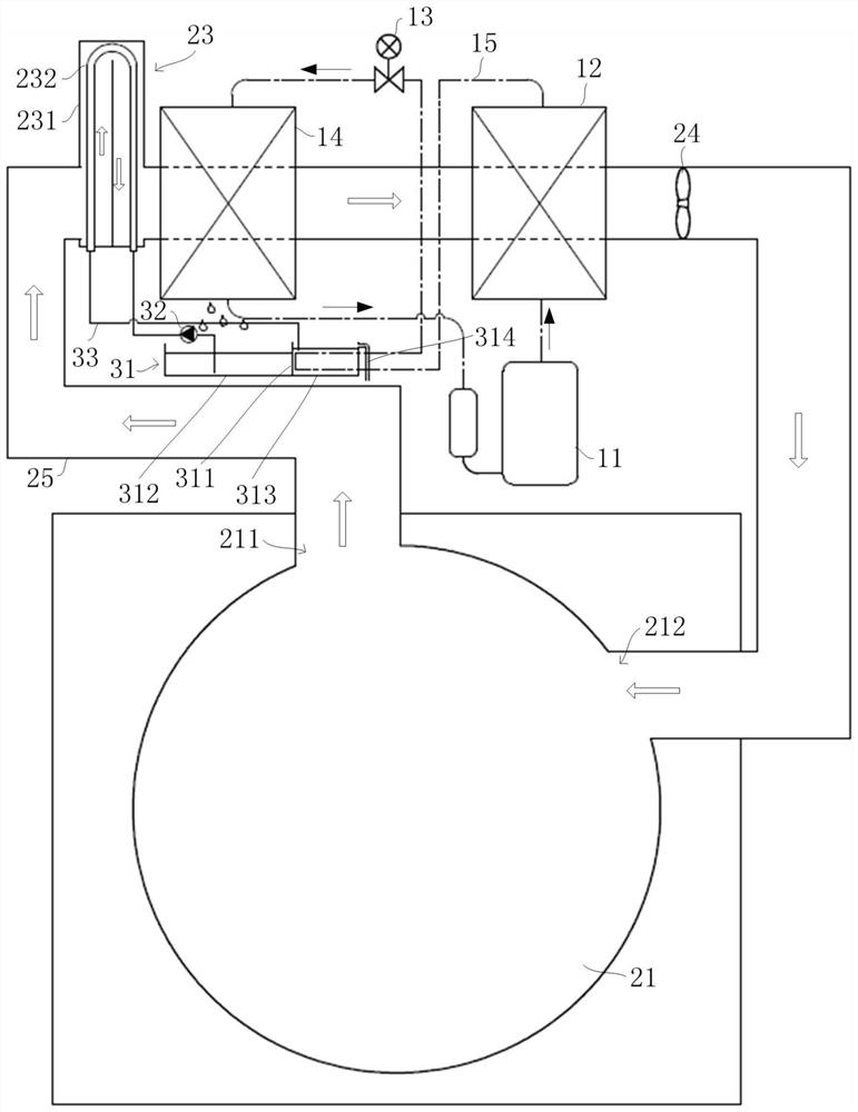
[0041] First refer to figure 2 , the first embodiment of the drying system of the present invention will be described. in, figure 2 It is a system diagram of the drying system in the first embodiment of the present invention.

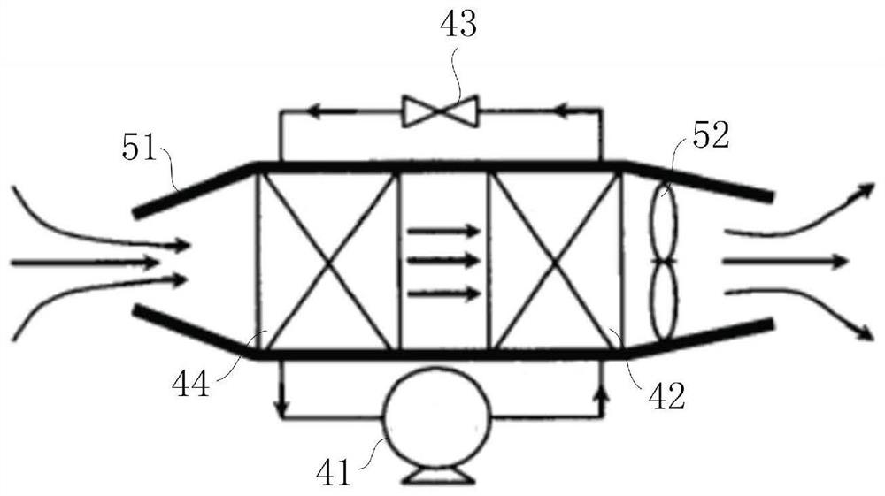
[0042] As mentioned in the background technology, in the existing drying system, as the moisture content of the clothes in the drying chamber gradually decreases, the relative humidity in the drying chamber is also getting smaller and smaller, and the air heated by the condenser is in the drying chamber The lowering range of the medium temperature also decreases, and the temperature of the air entering the evaporator and condenser continues to rise, which leads to the gradual weakening of the dehumidification capacity of the evaporator, and the dehumidification effect is getting worse, which results in longer drying time for clothes and lower power consumption of the system. is also increasing.

[0043] Such as figure 2 As shown, in order to solv...

Embodiment 2

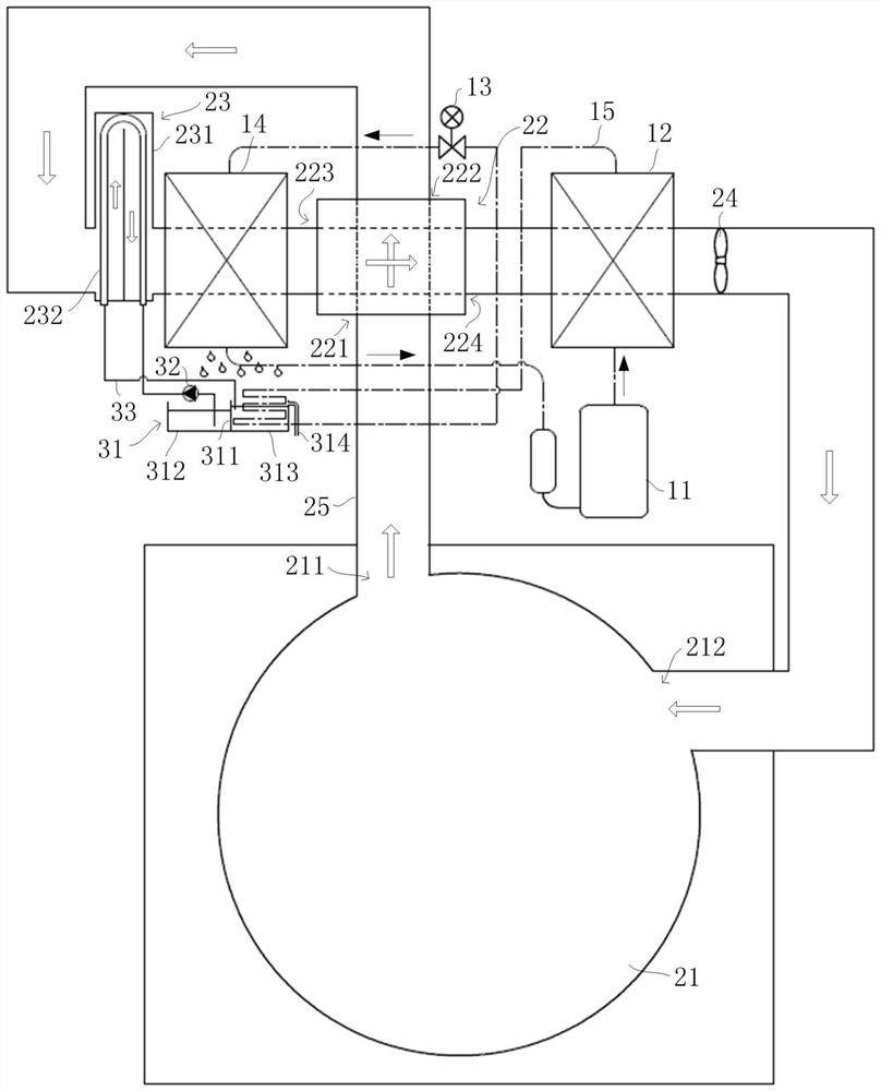
[0060] Refer below image 3 , to describe the second embodiment of the drying system of the present application. in, image 3 It is a system diagram of the drying system in the second embodiment of the present invention.

[0061] Such as image 3As shown, under the premise of keeping other structural settings unchanged in Embodiment 1, the drying system further includes a cascade heat exchanger 22, and the cascade heat exchanger 22 has a first inlet 221, a first outlet 222, a second inlet 223 and the second outlet 224, an air passage is formed between the first inlet 221 and the first outlet 222, another air passage is formed between the second inlet 223 and the second outlet 224, and the two air passages are intersected with each other , enabling cross-exchange of heat. The first inlet 221 communicates with the wet air outlet 211, the first outlet 222 communicates with the air inlet 2311 of the gas-liquid heat exchanger 23, the second inlet 223 communicates with the outle...

Embodiment 3

[0076] The present application also provides an integrated washing and drying machine, which includes a box body (not shown in the figure), an organic door is arranged on the box body, a water inlet assembly, a driving device and a washing tub assembly are arranged in the box body, The washing tub assembly includes an outer tub and an inner tub, the inner tub can hold clothes to be washed, the water inlet assembly can inject water into the outer tub, and the driving device can drive the inner tub to rotate so as to complete the washing of the clothes. This all-in-one washing and drying machine also includes the drying system described in the above embodiments, the outer cylinder is provided with a wet air outlet 211 and a dry air inlet 212, the outer cylinder, a gas-liquid heat exchanger 23, an evaporator 14, and a condenser 12 It is connected with fan 24 through air duct 25 to form an air circulation loop.

[0077] By setting the above-mentioned drying system in the washer-dr...


PUM


Abstract

The invention relates to the technical field of clothes treatment, in particular to a drying system and clothes treatment equipment comprising the same. The problems that an existing drying system islong in drying time and large in energy consumption are solved. The drying system comprises a refrigerant circulation loop, an air circulation loop and a cooling circulation loop, wherein the refrigerant circulation loop comprises a compressor, a condenser, a throttling element and an evaporator; the air circulation loop comprises a drying chamber, a gas-liquid heat exchanger, an evaporator and acondenser, an air inlet of the gas-liquid heat exchanger communicates with a wet air outlet of the drying chamber, an air outlet of the gas-liquid heat exchanger communicates with an inlet of the evaporator, an outlet of the evaporator communicates with an inlet of the condenser, and an outlet of the condenser communicates with a dry air inlet of the drying chamber; and the cooling circulation loop comprises a water pan, a water pump and a gas-liquid heat exchanger, a liquid inlet and a liquid outlet of the gas-liquid heat exchanger communicate with a first part and a second part of the waterpan respectively, and a refrigerant pipe part is arranged on the second part in a coiled mode. The dehumidification capacity of the evaporator can be guaranteed, and the drying energy consumption is reduced.

Description

technical field [0001] The invention relates to the technical field of clothes treatment, in particular to a drying system and clothes treatment equipment including the system. Background technique [0002] The schematic diagram of the existing heat pump drying system is as follows: figure 1 As shown, it mainly includes refrigerant circulation and humid air circulation. Among them, the refrigerant cycle mainly includes a compressor 41 , a condenser 42 , a throttling device 43 and an evaporator 44 , and the humid air cycle includes an air duct 51 , a fan 52 and a drying chamber connected to both ends of the air duct 51 . The condenser 42 and evaporator 44 in the refrigerant cycle are arranged in the air duct 51. During operation, the humid air in the drying chamber enters the air duct 51 from one end of the air duct 51 driven by the fan 52, and flows through the air duct 51 in turn. The evaporator 44 and the condenser 42 return to the drying chamber through the other end of...

Claims


Application Information

Patent Timeline
Patent Type & Authority Applications(China)
IPC IPC(8): D06F25/00D06F58/20D06F58/24
CPCD06F25/00D06F58/20D06F58/24
Inventor 罗荣邦王飞崔灿侯永顺常全成
Owner QINGDAO HAIER AIR CONDITIONER GENERAL CORP LTD
Why Eureka
Try Eureka