Manufacturing method of fluorinated cladding plastic optical fiber
A technology of plastic optical fiber and manufacturing method, applied in the directions of cladding optical fiber, coating, optics, etc., can solve the problems of affecting the coating efficiency, reducing the coating quality, and the lack of a winding mechanism of the coating device, so as to achieve uniform heat transfer, The effect of improving coating efficiency
- Summary
- Abstract
- Description
- Claims
- Application Information
AI Technical Summary
Problems solved by technology
Method used
Image
Examples
Embodiment 1
[0054] A method for manufacturing a fluorinated clad plastic optical fiber, comprising the steps of:
[0055] S1, preparing an optical fiber preform;
[0056] S2, preparing the fiber core; the specific steps are as follows:
[0057] Step 1. Melting and drawing the optical fiber preform, and cooling the drawn wire;
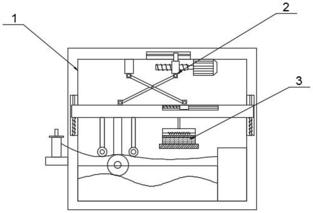
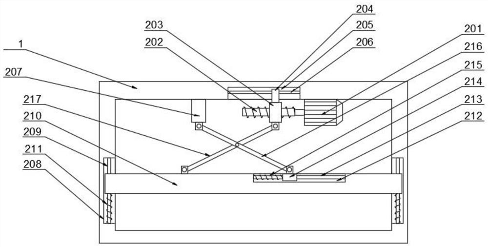
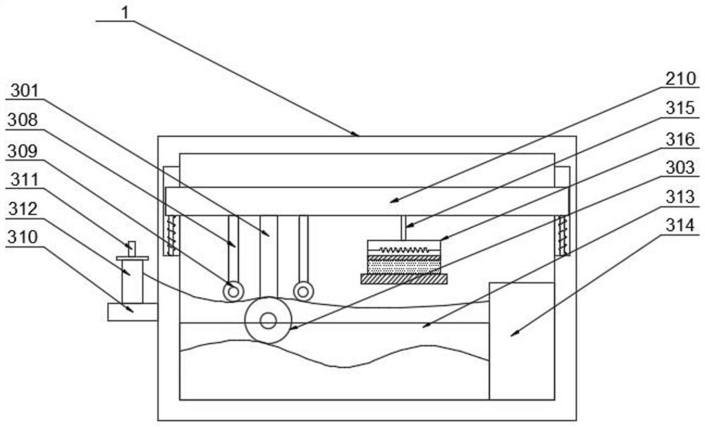
[0058] Step 2. Coating the optical fiber preform after the melting and drawing process by a coating device at a temperature of 45° C., so that the surface of the optical fiber preform is attached with a coating;
[0059] Step 3, putting the optical fiber preform coated with the coating into an ultraviolet curing furnace for curing treatment to obtain a fiber core;
[0060] S3. Put the fiber core into a fluorination furnace containing a fluorination agent, perform a fluorination reaction at 5°C for 20 hours, and form a fluoride cladding with a thickness of 5 μm on the surface of the fiber core to obtain a fluoride cladding plastic optical fiber .
[0061] The pr...
Embodiment 2
[0069] A method for manufacturing a fluorinated clad plastic optical fiber, comprising the steps of:
[0070] S1, preparing an optical fiber preform;
[0071] S2, preparing the fiber core; the specific steps are as follows:
[0072] Step 1. Melting and drawing the optical fiber preform, and cooling the drawn wire;
[0073] Step 2. Coating the optical fiber preform after the melting and drawing process by a coating device at a temperature of 55° C., so that the surface of the optical fiber preform is attached with a coating;
[0074] Step 3, putting the optical fiber preform coated with the coating into an ultraviolet curing furnace for curing treatment to obtain a fiber core;
[0075] S3. Put the fiber core into a fluorination furnace containing a fluorination agent, perform a fluorination reaction at 20°C for 30 hours, and form a fluorinated cladding with a thickness of 7 μm on the surface of the fiber core to obtain a fluorinated clad plastic optical fiber .
[0076] The...
Embodiment 3
[0084] A method for manufacturing a fluorinated clad plastic optical fiber, comprising the steps of:
[0085] S1, preparing an optical fiber preform;
[0086] S2, preparing the fiber core; the specific steps are as follows:
[0087] Step 1. Melting and drawing the optical fiber preform, and cooling the drawn wire;
[0088] Step 2. Coating the optical fiber preform after the melting and drawing process by a coating device at a temperature of 60° C., so that the surface of the optical fiber preform is attached with a coating;
[0089] Step 3, putting the optical fiber preform coated with the coating into an ultraviolet curing furnace for curing treatment to obtain a fiber core;
[0090] S3. Put the fiber core into a fluorination furnace containing a fluorination agent, perform a fluorination reaction at 30°C for 50 hours, and form a fluorinated cladding with a thickness of 12 μm on the surface of the fiber core to obtain a fluorinated clad plastic optical fiber .
[0091] The ...
PUM
| Property | Measurement | Unit |
|---|---|---|
| thickness | aaaaa | aaaaa |
Abstract
Description
Claims
Application Information
 - R&D
- Intellectual Property
- Life Sciences
- Materials
- Tech Scout
- Unparalleled Data Quality
- Higher Quality Content
- 60% Fewer Hallucinations
Browse by: Latest US Patents, China's latest patents, Technical Efficacy Thesaurus, Application Domain, Technology Topic, Popular Technical Reports.
© 2025 PatSnap. All rights reserved.Legal|Privacy policy|Modern Slavery Act Transparency Statement|Sitemap|About US| Contact US: help@patsnap.com


