
Strip steel rewinding mechanism for strip steel hot galvanizing production line

A winding mechanism and hot-dip galvanizing technology, applied in hot-dip galvanizing process, coiling strip, coating, etc., can solve the problems of reduced work efficiency, jealousy, low efficiency, etc., to improve work efficiency, easy to use, The effect of improving usability

Pending Publication Date: 2021-02-09
山东富海材料科技有限公司
View PDF0 Cites 1 Cited by
  • Summary
  • Abstract
  • Description
  • Claims
  • Application Information

AI Technical Summary

Problems solved by technology

[0003] In the existing technology, after the strip steel winding mechanism completes the strip steel winding, because it has no self-releasing function, the strip steel coil after winding cannot be automatically removed, and it needs to be removed manually, which reduces the work Efficiency, and envy consumes physical strength, resulting in a decrease in its practicability; and after the existing strip steel winding mechanism completes the strip steel winding, it needs to manually push the transport vehicle to move the strip steel coil, which cannot realize automatic winding transportation. Not very practical and not very efficient

Method used


Image

  • Strip steel rewinding mechanism for strip steel hot galvanizing production line
  • Strip steel rewinding mechanism for strip steel hot galvanizing production line
  • Strip steel rewinding mechanism for strip steel hot galvanizing production line

Examples


Embodiment Construction

[0023] The following will clearly and completely describe the technical solutions in the embodiments of the present invention with reference to the accompanying drawings in the embodiments of the present invention. Obviously, the described embodiments are only some, not all, embodiments of the present invention. Based on the embodiments of the present invention, all other embodiments obtained by persons of ordinary skill in the art without making creative efforts belong to the protection scope of the present invention.

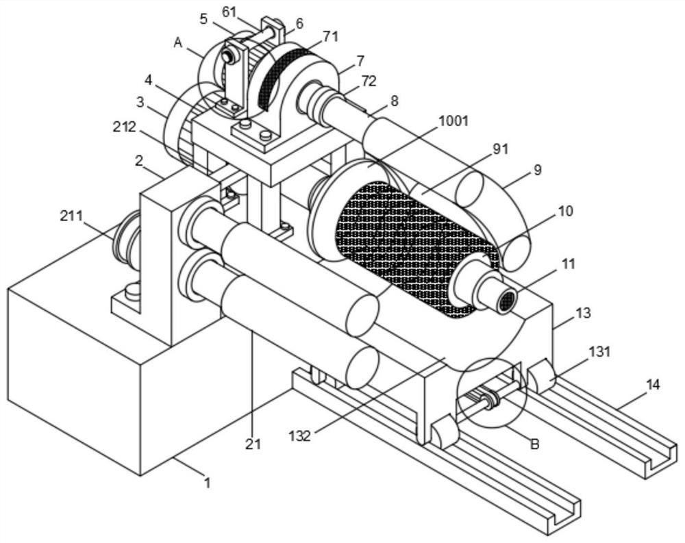
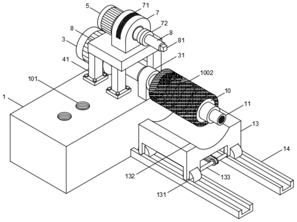
[0024] see Figure 1-5 , in an embodiment of the present invention, a strip steel winding mechanism for a hot-dip galvanizing production line includes a base 1 and a bracket 13, and a plurality of mounting holes 101 are provided at the top left of the base 1, and the mounting holes 101 Mounting seat 2 is installed on the top, guide roller group 21 is installed on the front end of the upper part of mounting seat 2, the first pulley 211 is installed on the rear ...


PUM


Abstract

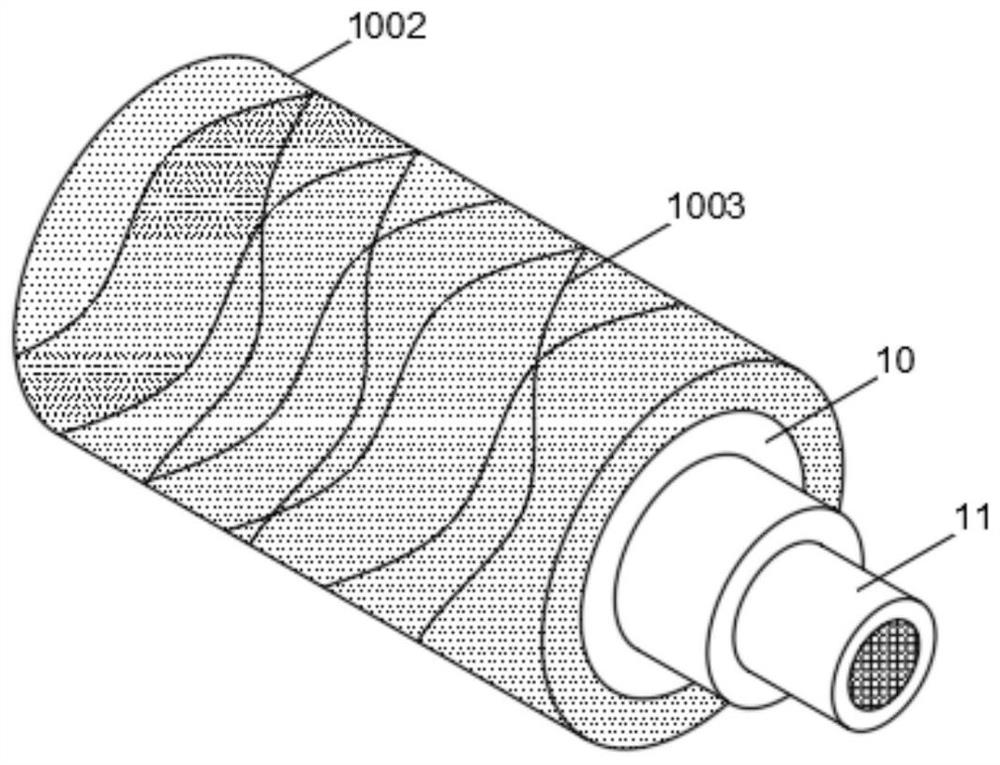
The invention discloses a strip steel rewinding mechanism for a strip steel hot galvanizing production line. The strip steel rewinding mechanism comprises a base and a support base, wherein a plurality of mounting holes are formed in the left part of the top end of the base; a mounting base is mounted above the mounting holes; a guide roller group is mounted at the front end of the upper part of the mounting base; a first belt wheel is mounted at the rear end of the lower part of the mounting base; a first belt is mounted on the first belt wheel; a first motor is mounted at the right side of the mounting base; a shaft base is mounted on a rotary shaft at the right side of the first motor; a limiting plate is mounted at the front end of the shaft base; a rewinding roller is mounted at the front end of the limiting plate; an expanding ring sleeves outside the rewinding roller; a plurality of anti-sliding grains are arranged on the surface of the expanding ring; an inflator is mounted atthe front end of the rewinding roller; the support base is in sliding connection to a slide rail through a slide wheel; and the slide wheel is driven by a driver on the lower part of the support base.After a steel strip drops into an arc-shaped slot, a drive mechanism is started for linkage of a slide wheel, and the support base can be moved out along with the steel strip without manual transportation, and thus, the strip steel rewinding mechanism is convenient in use, quick, and beneficial for improving work efficiency.

Description

technical field [0001] The invention relates to the field of strip steel, in particular to a strip steel winding mechanism used in a strip steel hot-dip galvanizing production line. Background technique [0002] Steel is easy to rust in air and water, while the corrosion rate of zinc in the atmosphere is only 1 / 15 of the corrosion rate of steel in the atmosphere. Galvanized steel sheet is to protect the steel sheet with a micro-dense galvanized layer from corrosion. It refers to the conveyor belt made of carbon steel as the traction and carrying member of the belt conveyor, and can also be used to bundle goods. It is produced by various steel rolling enterprises to meet the needs of industrial production of various metal or mechanical products in different industrial sectors. A narrow and long steel plate, steel strip is also called strip steel, the width is within 1300mm, and the length is slightly different according to the size of each coil. Strip steel is generally suppl...

Claims


Application Information

Patent Timeline
Patent Type & Authority Applications(China)
IPC IPC(8): C23C2/06C23C2/40B65H18/10B65H75/24B65H19/30B65H23/00B65H23/032B65H75/12
CPCC23C2/003C23C2/06C23C2/40B65H18/10B65H75/243B65H19/30B65H23/00B65H23/032B65H75/12
Inventor 李清国
Owner 山东富海材料科技有限公司
Learn More