Large plate shearing machine hydraulic system

A technology of hydraulic system and shearing machine, applied in the direction of fluid pressure actuating system components, shearing devices, mechanical equipment, etc., can solve the problems of decreasing shearing efficiency, speeding up the return speed, long empty stroke, etc., to reduce the oil circuit The effect of whistling, guaranteeing the downlink speed, and speeding up the return speed

Pending Publication Date: 2021-02-09
ANHUI DONGHAI MACHINE MFG CO LTD
View PDF0 Cites 1 Cited by
  • Summary
  • Abstract
  • Description
  • Claims
  • Application Information

AI Technical Summary

Problems solved by technology

[0003] First: the return stroke of the ordinary accumulator, the upper knife rest cannot be stopped at any position, resulting in at least two people operating at the same time to complete the adjustment of the knife edge gap, and one of them is on the top of the machine by controlling the high-pressure ball valve to slowly drain the oil , so that the upper knife rest goes up a little bit from the bottom dead center position, every time it goes up a little bit, and then the person at the machine table position uses a feeler gauge to fine-tune the gap between the knife edges a little bit, so as to achieve the best cutting effect of the shearing machine, the above knife adjustment The method requires two people to cooperate with the operation at the same time, and the efficiency of knife adjustment is low
[0004] Second: The main oil cylinder is limited due to the oil suction method. In the case of heavy weight of the upper tool holder, when the upper tool holder goes down rapidly, a vacuum will be generated in the rodless chamber of the main oil cylinder, and there is no timely replenishment of hydraulic oil, resulting in the failure of the main oil cylinder. The rodless chamber is sucked empty, resulting in hydraulic impact; the shearing speed of the upper tool holder can only depend on the displacement of the hydraulic pump and the speed of the driving motor of the hydraulic pump, and the cost is high
[0005] Third: In the hydraulic system of the original large-scale gate shearing machine, when the return flow of the upper tool holder is large, an electromagnetic overflow valve is used to open a return branch to allow the hydraulic oil to return to the oil tank from multiple branches or thicken The method of oil return pipe speeds up the return stroke and reduces the phenomenon of howling in the oil circuit. Not only is the effect not obvious, but the cost is also high, and the design of the valve block is more difficult.
[0006] Fourth: In the hydraulic system of the original large-scale gate shearing machine, most of the valve groups generally adopt the slide valve structure. Due to the sealing and structural reasons, the slide valve structure has leakage problems over time, and the product failure rate becomes higher.
[0007] Fifth: In the hydraulic system of the original large-scale gate shearing machine, the shearing angle increases or decreases, and the action speed cannot be adjusted, which is a constant speed. At this time, if the system flow is too large, the action will be fast, and the user will Difficult to locate a specific angle value
[0008] Sixth: In the hydraulic system of the original large-scale gate-type shearing machine, when all the solenoid valves are de-energized, the upper knife rest can only be raised to the top dead center position, and the upper knife rest moves downward from the top dead center position. When shearing a thin plate, the empty stroke is too long, and the shearing efficiency decreases

Method used


Image

  • Large plate shearing machine hydraulic system

Examples


Embodiment 1

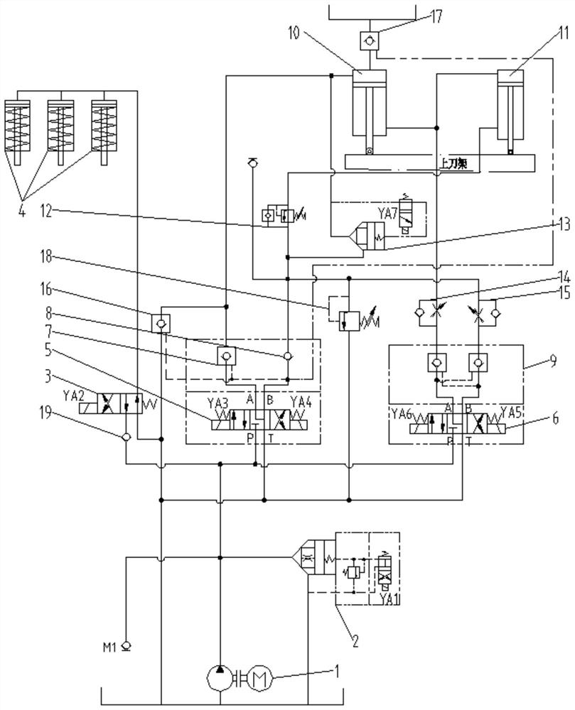
[0045]The upper tool rests fast downward shearing action: solenoid valve four YA4, solenoid valve five YA5, solenoid valve six YA6, solenoid valve seven YA7 are all de-energized, solenoid valve one YA1, solenoid valve two YA2 is first powered, and hydraulic pump 1 is used. The hydraulic oil first enters the rodless cavity of the material pressing cylinder 4 through the one-way valve 19 and the two-position four-way reversing valve 3, so that the material pressing cylinder 4 first presses the workpiece to be cut.

[0046]After 0.5S, solenoid valve three YA3 is energized, and the left position of three-position four-way reversing valve 5 is connected. At this time, P port on three-position four-way reversing valve 5 is connected to port A, and port B is connected to T The hydraulic oil from the hydraulic pump 1 enters the rodless cavity of the main cylinder 10 through the three-position four-way reversing valve 5 and the hydraulic control check valve 7 to push the piston rod of the main ...

Embodiment 2

[0052]The upper tool rest moves upward and backward: solenoid valve two YA2, solenoid valve three YA3, solenoid valve five YA5, solenoid valve six YA6 are all de-energized, solenoid valve one YA1, solenoid valve four YA4, solenoid valve seven YA7 are energized, three positions four The right position of the one-way reversing valve 5 is turned on. At this time, the hydraulic oil in the rodless cavity of the pressure-feeding cylinder 4 returns to the tank through the two-position four-way reversing valve 3 under the action of the spring in the pressure-feeding cylinder 4; The P port on the four-way reversing valve 5 is connected to the B port, and the A port is connected to the T port. The hydraulic oil from the hydraulic pump 1 passes through the three-position four-way reversing valve 5, the one-way valve 8 and the one-way sequence The valve 12 enters the rod cavity of the auxiliary cylinder 11, pushing the piston rod of the auxiliary cylinder 11 upward, and the hydraulic oil in the...

Embodiment 3

[0057]The shear angle of the upper tool post increases: solenoid valve two YA2, solenoid valve three YA3, solenoid valve four YA4, solenoid valve six YA6 are all de-energized, solenoid valve one YA1, solenoid valve five YA5, solenoid valve seven YA7 are energized, three The right position of the two-position four-way reversing valve 6 is connected. At this time, the P port and the B port of the three-position four-way reversing valve 6 are connected, and the A port is connected to the T port. The combined valve 13 is in the closed state, and the main The rodless cavity of the oil cylinder 10 is closed. The hydraulic oil discharged by the hydraulic pump 1 passes through the three-position four-way reversing valve 6 and the hydraulic control check valve on the right side of the two-way hydraulic lock 9, the one-way throttle valve 15 and the one-way The one-way valve in the sequence valve 12 enters the rod cavity of the auxiliary cylinder 11 and pushes the piston rod of the auxiliary c...


PUM


Abstract

The invention discloses a large plate shearing machine hydraulic system which comprises a hydraulic pump, a combined cartridge valve, a two-position four-way reversing valve, a pressing oil cylinder,a first three-position four-way reversing valve, a second three-position four-way reversing valve, a first hydraulic control one-way valve, a first one-way valve, a two-way hydraulic lock, a main oilcylinder, an auxiliary oil cylinder, a one-way sequence valve, a combined valve, a first one-way throttle valve and a second one-way throttle valve; the rapid descending shearing action of an upper knife rest is realized; the rapid ascending returning action of the upper knife rest is realized, and the descending speed of the upper knife rest and the stability of the hydraulic system are ensured;the upper knife rest can be locked at any position, the structure is reliable in locking and free of leakage, and the position of the upper knife rest can be locked for a long time; and the shearing angle adjusting action speed is controlled by adjusting knobs of the first one-way throttle valve and the second one-way throttle valve.

Description

Technical field[0001]The invention belongs to the technical field of hydraulic systems for shears. Specifically, the invention relates to a hydraulic system for large shears.Background technique[0002]The hydraulic system of the original large-scale guillotine shears has the following problems during the working process:[0003]First: the return stroke of the ordinary accumulator, the upper tool post cannot stop at any position, which results in at least two people operating at the same time when adjusting the blade gap. One of them controls the high pressure ball valve on the top of the machine to slowly discharge the oil. , Make the upper tool post go up from the bottom dead center position a little bit, and every time you go up a little bit, then the person at the working table of the machine uses a feeler gauge to finely adjust the knife edge gap to achieve the best cutting effect of the shearing machine. The method requires two people to work together at the same time, and the eff...

Claims


Application Information

Patent Timeline
Patent Type & Authority Applications(China)
IPC IPC(8): F15B21/08F15B11/16F15B11/04F15B13/06F15B21/00B23D15/06B23D15/14
CPCB23D15/06B23D15/14F15B11/04F15B11/16F15B13/06F15B21/008F15B21/087
Inventor 石贤锋石贤林郑盼盼孙绵祥
Owner ANHUI DONGHAI MACHINE MFG CO LTD
Why Eureka
Try Eureka