Novel cylindrical button battery

A button battery and cylinder technology, applied in the field of new cylindrical button batteries, can solve problems such as corrosion, battery gas, burrs that are easy to pierce, and achieve the effect of ensuring stability

Pending Publication Date: 2021-02-09
大器(深圳)创新科技有限公司
View PDF7 Cites 0 Cited by
  • Summary
  • Abstract
  • Description
  • Claims
  • Application Information

AI Technical Summary

Problems solved by technology

[0003] However, after the upper and lower heads are packaged, the surface is a flat aluminum-plastic film, but after forced physical punching, the edge sealing of the curved surface will be physically impacted. After the aluminum layer in the middle of the aluminum-plastic is damaged, the battery will be charged, discharged and stored. , the electrolyte will continuously corrode the aluminum layer, resulting in the generation of gas and liquid leakage after the battery is stored. In addition, the existing battery core is made of separator paper sandwiched between the positive and negative electrodes, but the material of the positive and negative electrodes There will be some burrs on the edge, and the burrs can easily pierce the separator paper, which will cause damage to the inside of the battery

Method used


Image

  • Novel cylindrical button battery
  • Novel cylindrical button battery
  • Novel cylindrical button battery

Examples


Embodiment 1

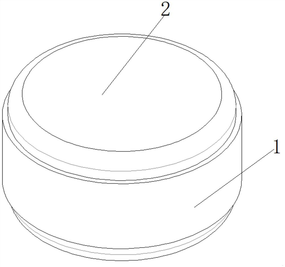
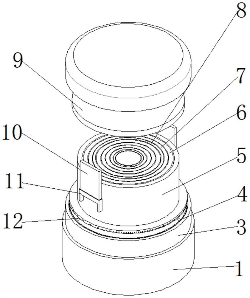
[0028] see Figure 1-2 , a novel cylindrical button cell, comprising membrane case one 2, membrane case two 3 and winding core 5, membrane case one 2 being installed above membrane case two 3, winding core 5 being installed on the inner side of membrane case two 3, membrane case An anti-corrosion sheet 4 is fixedly installed on the inner side of the first 2, and the anti-corrosion sheet 4 can play a protective role on the inner winding core 5, and a sealing gasket 9 is fixedly installed on the inner side of the membrane shell two 3, and the sealing gasket 9 can protect the winding core 5. To protect the winding core 5 from damage due to external force, a protective sleeve 1 is fixedly installed at the junction of the membrane shell 1 2 and the membrane shell 2 3, and the connection of the membrane shell 1 2 and the membrane shell 2 3 can be fixed through the protective sleeve 1 Protection at the junction of membrane shell 1 2 and membrane shell 2 3 to avoid liquid leakage caus...

Embodiment 2

[0037] Based on Example 1, such as Figure 1-2 , A wool top 12 is fixedly installed under the core 5 , the negative electrode ear 11 runs through the wool top 12 , and the bottom of the core 5 can be protected by the wool top 12 .

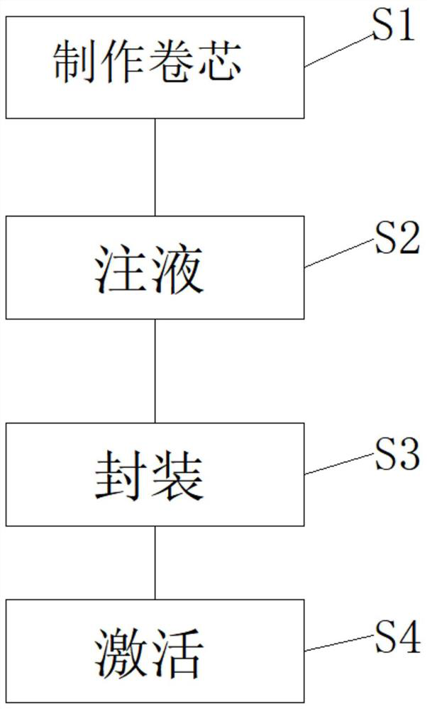
[0038] Working principle: When installing the winding core 5, first install the top 12 on the bottom of the membrane shell 12, and then install the winding core 5 above the top 12. During installation, the negative electrode ear 11 runs through the top 12, and then connects to the membrane shell 12. The inner side of shell one 2 is dripped with electrolyte.

[0039] When encapsulating, high-frequency heating is used to seal the junction of membrane shell 1 2 and membrane shell 2 3, and then the anti-corrosion sheet 4 can prevent the inner solution from corroding the shell, and then the protective sleeve 1 is fixed on the membrane shell 1 2 and membrane shell 2 3, after the installation is completed, it is sealed at high temperature, so that the pr...


PUM


Abstract

The invention relates to the technical field of batteries, and discloses a novel cylindrical button battery which comprises a membrane shell I, a membrane shell II and a roll core, the membrane shellI is mounted above the membrane shell II, the roll core is mounted on the inner side of the membrane shell II, an anti-corrosion sheet is fixedly mounted on the inner side of the membrane shell I, anda sealing gasket is fixedly mounted above the inner side of the membrane shell II; and a protective sleeve is fixedly mounted at the joint of the membrane shell I and the membrane shell II. Accordingto the novel cylindrical button battery, high-frequency heating packaging is carried out on the joint of the membrane shell I and the membrane shell II by using high-frequency packaging equipment, sothat the stability of the packaging performance is ensured, and meanwhile, an anti-corrosion sheet can prevent an inner side solution from corroding the membrane shell I and the membrane shell II, sothat the situations of gas expansion, liquid leakage and the like caused by poor packaging are avoided.

Description

technical field [0001] The invention relates to the technical field of batteries, in particular to a novel cylindrical button battery. Background technique [0002] At present, the common button battery in the industry, its packaging technology is that the upper and lower aluminum-plastic film shells are punched, the copper mold is heat-sealed, and then the upper and lower steel shells are hooped and sealed to form a button battery similar to a beer bottle cap. [0003] However, after the upper and lower heads are packaged, the surface is a flat aluminum-plastic film, but after forced physical punching, the edge sealing of the curved surface will be physically impacted. After the aluminum layer in the middle of the aluminum-plastic is damaged, the battery will be charged, discharged and stored. , the electrolyte will continuously corrode the aluminum layer, resulting in the generation of gas and liquid leakage after the battery is stored. In addition, the existing battery co...

Claims


Application Information

Patent Timeline
IPC IPC(8): H01M10/04H01M50/109H01M50/145H01M50/184H01M50/186
CPCH01M10/0427H01M10/0431Y02E60/10Y02P70/50
Inventor 程可武
Owner 大器(深圳)创新科技有限公司
Why Eureka
Try Eureka