
A landing gear assembly and testing integrated equipment

A landing gear and equipment technology, applied in metal processing equipment, measuring devices, instruments, etc., can solve the problems of delivery with defects, heavy workload of repeated handling, and high labor intensity, so as to improve the efficiency of assembly and inspection and avoid manual Effects of recording data and increasing the level of automation

Active Publication Date: 2022-04-08
CHENGDU AIRCRAFT INDUSTRY GROUP
View PDF0 Cites 0 Cited by
  • Summary
  • Abstract
  • Description
  • Claims
  • Application Information

AI Technical Summary

Problems solved by technology

[0003] At present, the landing gear manufacturing industry still mainly relies on skilled workers to use simple fixtures and hand tools for assembly. Usually, one of the two main structural parts (outer cylinder or piston rod) of the buffer is fixed on the fixture. The assembly is carried out by manual lifting or crane assistance, and after assembly, the whole is transported to the special inspection fixture to inspect the technical indicators such as stroke, length, angle, etc. The inspection process also mainly relies on manual push and pull of the piston rod, and is measured by ordinary measuring tools and digitalized. The level is low, the workload of repeated handling in the work is heavy, and the labor intensity is high; during assembly, it is impossible to accurately judge whether the seal is intact after it is put into the cylinder, and only rely on the experience and feeling of the operator to judge, often resulting in subsequent airtightness testing. defect delivery

Method used


Image

  • A landing gear assembly and testing integrated equipment
  • A landing gear assembly and testing integrated equipment
  • A landing gear assembly and testing integrated equipment

Examples


Embodiment 1

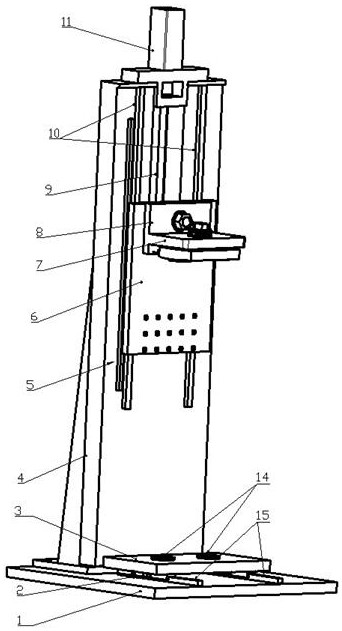
[0043] An integrated equipment for landing gear assembly and testing, such as Figure 1-Figure 6 , including a mechanical system, a measurement system and a control system, the mechanical system includes a base plate 1, a lower workbench 3, a column 4, a slider 6, an upper workbench 7 and a quick-change positioning block 14; the lower workbench 3 is slidably installed On the base plate 1, the column 4 is fixedly installed on the base plate 1, the slider 6 is connected to the front of the column 4 through a screw structure, and the upper workbench 7 and the slider 6 are fixedly connected; There is a quick-change positioning block 14 for quick loading and unloading of the fixture;

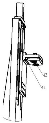
[0044]Described measuring system comprises pull-pressure sensor 12, displacement sensor 16, grating ruler 5 and data processor to form; Described pull-pressure sensor 12 is arranged on slide block 6 or upper workbench 7, and displacement sensor 16 is also arranged on slide block 6 Or on the upper wo...

Embodiment 2

[0062] This embodiment is on the basis of embodiment 1, as Figure 5 , the mechanical system also includes a lower jig J1, an upper jig J2 and a middle jig J3, the lower jig J1 is fixed on the column 4, the upper jig J2 is fixed on the upper workbench 7, and the middle jig J3 is fixed on the slide Block 6 on.

[0063] The structure of the screw mandrel connected between the slider 6 and the column 4 is: the column 4 is provided with a screw mandrel 9 and a first guide rail 10, and the slider 6 is provided with a ball nut 13 sleeved on the screw mandrel 9, so The slider 6 is sleeved on the first guide rail 10 .

[0064] The upper table 7 and the slider 6 are connected by a T-shaped bracket 8, the top surface of the T-shaped bracket 8 is connected to the slider 6 through the first bearing structure, and the lower end surface of the T-shaped bracket 8 is connected by the second bearing structure Connect to Workbench 7.

[0065] The first bearing structure includes a threaded s...


PUM


Abstract

An integrated equipment for landing gear assembly and testing, including a mechanical system, a measurement system and a control system. The mechanical system includes a bottom plate, a lower workbench, a column, a slider, an upper workbench and a quick-change positioning block; the lower workbench is slidably installed on On the bottom plate, the column is fixedly installed on the bottom plate, the slider is connected to the front of the column through a screw structure, and the upper worktable is fixedly connected to the slider; the lower worktable is equipped with a quick-change positioning block; the measurement system includes a tension sensor, a displacement sensor , a grating ruler and a data processor; the tension sensor is set on the slider or the upper worktable, the displacement sensor is also set on the slider or the upper worktable, and the grating ruler is set on the column, which can accurately detect the movement of the slider up and down. Position; the data collected by tension and pressure sensors, displacement sensors and grating rulers are uploaded to the data processor for data processing; the control system includes a motor, a motion controller, a PLC and a host computer that are electrically connected in turn.

Description

technical field [0001] The invention relates to the field of landing gear struts, in particular to an integrated equipment for assembling and testing landing gear. Background technique [0002] Due to the compact and complex structure of aircraft landing gear pillars, it is difficult to assemble them by putting tubes, sleeves, sealing rings, etc. inside the deep holes to form a multi-layer structure. The buffer assembly process is usually divided into three stages: initial assembly, hard assembly and test. The initial assembly process roughly includes: subassembly (without installing seals) - trial assembly - detection size - repair adjustment - motion detection - disassembly and cleaning; The assembly process generally includes: seal assembly - subsection assembly - cylinder rod alignment assembly - size inspection; the test mainly includes: air tightness inspection - oil and gas filling - running-in test - high and low temperature test - static pressure curve test, etc. ...

Claims


Application Information

Patent Timeline
Patent Type & Authority Patents(China)
IPC IPC(8): G01D21/02B23P19/00
CPCG01D21/02B23P19/00
Inventor 张文光李国伟郑思来李国华
Owner CHENGDU AIRCRAFT INDUSTRY GROUP
Learn More