[0038]The present invention will be further described in detail below with reference to the drawings and specific embodiments.
[0039]The measurement of protection system response time mainly measures the response time of each protection system logic. For the response time test of each logic, the trigger of an input signal that needs to be connected to this logic is the reference point for the start of time recording acquisition, and then the output signal of this logic is selected as the reference point for the end of time recording acquisition.
[0040]The whole measurement process is mainly divided into two parts: signal switching and measurement time.
[0041]Signal switching: It takes about 10-30 minutes, depending on the number of switching signals and the difficulty of disconnecting and wiring the cabinet.
[0042]Measurement time: about 1 to 2 minutes, used for signal multiple triggering, recovery and recorder data recording.
[0043]From the above empirical data, it can be known that the working time of the protection system response time test is mainly used for signal switching. The main difficulties of signal switching are:
[0044]There are few test cables across the plant;
[0045]There are many terminal locations for test cables in each plant;
[0046]There are many workshops for switching operations;
[0047]Limited access to measurement signals at the same time;
[0048]Based on this feature, the efficiency of the test can be greatly improved by improving the signal switching link. A fast switching circuit can be added to each plant, this switching circuit mainly realizes the rapid switching of more signals than less.
[0049]As shown in the figure, the signal switching circuit is based on the principle of isolation between the relay control circuit and the controlled circuit. 4 relays are connected in parallel to form a modular switch, and then the modular switch is cascaded to form a two-stage cascade circuit. The signal switching circuit sends a switch control command to each relay, and the corresponding relays act to bridge the channel of the selected input and conduct it to the output end, thereby realizing the rapid switching of the signal measured by the response time of the protection system.
[0050]The following is the implementation of the specific circuit:
[0051]The fast switching circuit is built based on relays. For the measurement of response time, the function of the switching circuit is to select and switch the measurement circuit. The part connected to the measurement circuit must not have components with delayed response time such as electronic components and cannot affect the signal transmission time of the measured circuit. The controlled end of the relay is the on and off of the metal switch. It is connected to the measurement circuit and will not delay the signal. The control end is an electronic component that is connected to the control command signal to realize the relay Fast action (the action time is in the millisecond level).
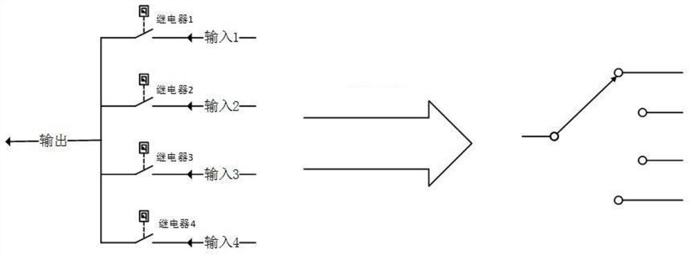
[0052]Through the parallel connection of relays, the signal can be more selected and less switched. Such asfigure 1 As shown, 4 independent relays and their respective controlled circuits are connected in parallel to form a 4-channel selection switch. Through the control instructions to the four relays, the signal can be selected from 1 to 4. The specific implementation is as follows:
[0053]4 relays are all disconnected, the selector switch is in the working state, and no selection signal is output;
[0054]Relay 1 is closed, other relays are disconnected, and the output of the selector switch selects input signal 1;
[0055]Relay 2 is closed, other relays are disconnected, and the output of the selector switch selects input signal 2;
[0056]Relay 3 is closed, other relays are disconnected, and the output of the selector switch selects input signal 3;
[0057]Relay 4 is closed, other relays are disconnected, and the output of the selector switch selects input signal 4;
[0058]If 4 relays are present at the same time and only 1 is closed, the selection switch unit can correctly select the module.
[0059]The 4 out of 1 selector switch is used as a modular switch, and a switching circuit with more and less options can be realized through the cascade combination of multiple modular switches. Such asfigure 1 As shown, the circuit diagram of each 4 out of 1 selection unit is simplified for subsequent circuit diagram combinations.
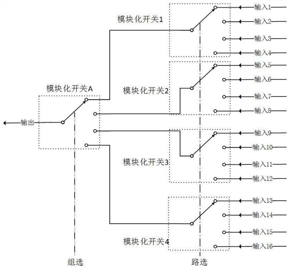
[0060]Select multiple signals through grouping and classification. Such asfigure 2 As shown, in the 16-to-1 fast switching circuit, 16 inputs are classified into 4 groups: the first group is inputs 1 to 4, the second group is inputs 5 to 8, the third group is inputs 9 to 12, and the fourth group is Enter 13~16. Each group is switched by a modular switch for selecting specific conduction signal lines. The modular switch used is divided into two levels, the first level is group selection, which is used to select "which group of input for the output signal", and the second level is path selection, which is used to select each group of input signals. Which signal is used as the output of the group". Through the cascade mode of group selection and road selection of modular switches, a switching circuit of 16 selections is realized.
[0061]When one of the 16 inputs is selected as the output, the contacts of the modular switch relays at all levels are closed to "bridge" this channel into a hard-wired path, thereby providing a channel for the input signal to be transmitted to the output. Such asfigure 2 As shown, the modular switch 1 of the road selection is selected as input 1, that is, the first group has selected input 1 as output; the modular switch 2 of road selection is selected as input 4, that is, the second group has selected input 4 as output; The selected modular switch 3 is selected as input 9, that is, the third group has selected input 9 as output; the modular switch 4 of the way selection is selected as input 13, that is, the fourth group has selected input 13 as output; and the group-selected module The switch A is selected as the first group of output, so the 16-to-1 fast switching circuit output selects the first group of input 1.
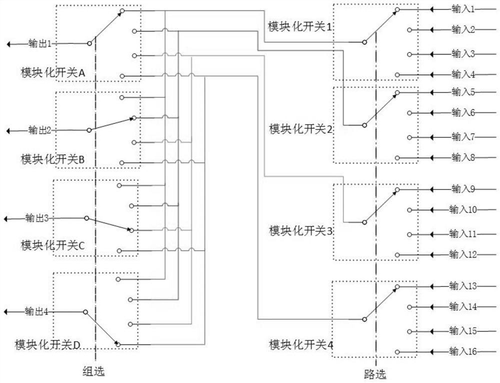
[0062]Such asimage 3As shown, the modular switch A of the group selection can be expanded to 4 in the same wiring manner, and the signal switching of 16 selections can be realized.image 3In, the modular switch 1 of the road selection is selected as input 1, the modular switch 2 is selected as input 4, the modular switch 3 is selected as input 9, the modular switch 4 is selected as input 13, and the modular switch A of group selection is selected For the first output, modular switch B is selected as the second output, modular switch C is selected as the third output, and modular switch D is selected as the fourth output. This is achieved: Input 1 is selected for output 1, input 5 is selected for output 2, input 9 is selected for output 3, input 13 is selected for output 4, and the signal switching selection of 16 out of 4 is completed.
[0063]Through the modular switch and cascade bridge of the relay, a 16-select 4 fast switching circuit is formed. The number of signals in the protection system of each nuclear power plant can be changed by changing the number of relays included in the modular switch to achieve 5 out of 25, 6 out of 36, 7 out of 49, 8 out of 64, 9 out of 81, 10 out of 100, etc. The switch combination realizes the rapid switch of the signal of the nuclear power plant protection system response time measurement.
[0064]Applying this circuit to the measurement of the response time of the protection system can achieve rapid signal switching. In the test of the response time measurement of the protection system, each plant is equipped with a fast switching circuit, the input end of the circuit is connected to all the test signals of the plant, and the output end is connected to the cable that is sent to the recorder across the plant. When performing the test, control the action of the relay in the fast switching circuit, connect the output terminal to the required signal input terminal, and send it to the recorder for response time measurement. Take the measurement of the response time of one channel input signal RCS005MP in the voltage regulator's high pressure three shutdown logic as an example. During the measurement, by inputting a fast switching command to the circuit, the fast switching action of the switching circuit in each plant is:
[0065]One-channel plant switching circuit: output 1 fast switching circuit switches to input signal-RCS005MP, output 2 fast switching to input signal-one channel shutdown signal;
[0066]Two-channel plant switching circuit: output 2 fast switching circuit switches to input signal-two-channel shutdown signal;
[0067]Three-channel plant switching circuit: output 2 fast switching circuit switches to the input signal-three-channel shutdown signal;
[0068]Four-channel plant switching circuit: output 2 fast switching circuit switches to the input signal-four-channel shutdown signal;
[0069]Computer room switching circuit switching: to the corresponding test signal to the output terminal of the test device such as the recorder.
[0070]After the fast switching is completed, the signal generator injection and the line bridging of the recorder are completed, and then the trigger signal is injected through the signal generator, and the RCS005MP regulator pressure high three shutdown response time can be obtained through the recorder.
[0071]The fast switching circuit based on modularization and cascade bridging combination realizes fast and accurate switching of the protection system, and makes full use of the principle of fast circuit response time, reducing the switching time from 10-30 minutes (manual) to 1 second (circuit) , The multiple level improves the efficiency of the response time measurement of the protection system.
[0072]The examples of the present invention are described above with reference to the accompanying drawings, but the present invention is not limited to the above-mentioned specific embodiments. The above-mentioned specific embodiments are only illustrative and not restrictive. Those of ordinary skill in the art are Under the enlightenment of the invention, many forms can be made without departing from the purpose of the invention and the protection scope of the claims, and these all fall within the protection scope of the invention.