
High common-mode rejection transmission line based on double-layer half-mode comb-shaped substrate integrated waveguide
A substrate-integrated waveguide, high common-mode suppression technology, applied in waveguides, waveguide-type devices, circuits, etc., can solve the problems of high radiation loss, limited application scope, etc., to broaden the application scope, be conducive to miniaturization, high common The effect of mode signal suppression
- Summary
- Abstract
- Description
- Claims
- Application Information
AI Technical Summary
Problems solved by technology
Method used
Image

Examples
Embodiment Construction
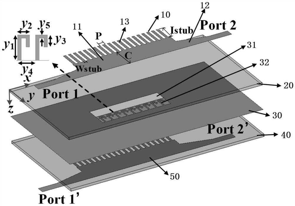
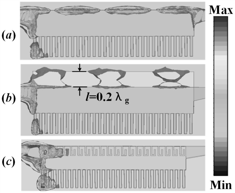
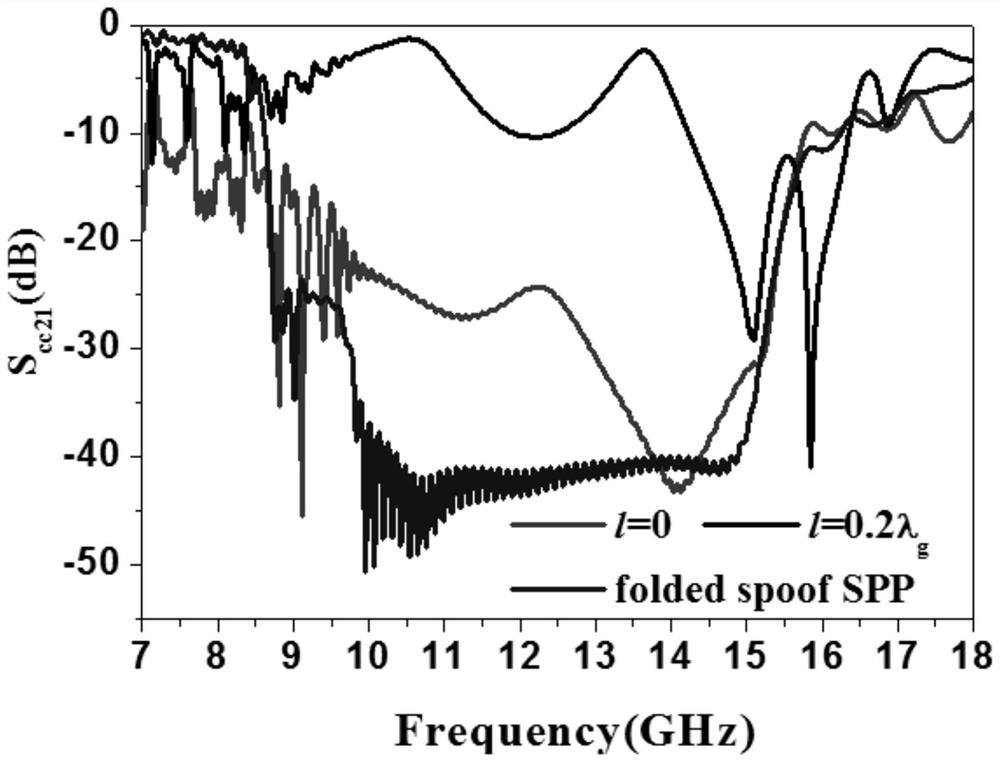
[0037] The present invention will be further described in detail below in conjunction with the accompanying drawings and specific preferred embodiments.
[0038] In the description of the present invention, it should be understood that the orientations or positional relationships indicated by the terms "left side", "right side", "upper", "lower" are based on the orientations or positional relationships shown in the accompanying drawings, and are only For the purpose of describing the present invention and simplifying the description, rather than indicating or implying that the device or element referred to must have a specific orientation, be constructed and operate in a specific orientation, "first", "second" and the like do not represent components importance, and therefore should not be construed as limiting the invention. The specific dimensions used in this embodiment are only for illustrating the technical solution, and do not limit the protection scope of the present in...
PUM
| Property | Measurement | Unit |
|---|---|---|
| length | aaaaa | aaaaa |
| width | aaaaa | aaaaa |
| length | aaaaa | aaaaa |
Abstract
Description
Claims
Application Information