
Low-output ripple power factor correction converter

A technology of power factor correction and converter, which is applied in the direction of output power conversion device, conversion of AC power input into DC power output, conversion of DC power input into DC power output, etc. Safety, increase the volume of the converter and other issues, to achieve the effect of large voltage stress, reduce volume and cost, and reduce voltage stress

Inactive Publication Date: 2021-02-12
SICHUAN UNIV
View PDF4 Cites 11 Cited by
  • Summary
  • Abstract
  • Description
  • Claims
  • Application Information

AI Technical Summary

Problems solved by technology

[0014] However, in this solution, the front stage is a Boost converter, and the voltage stress of the switching tube is large
n outputs require n inductors, which increases the volume of the converter
In addition, the LED driver is a non-isolated structure, which cannot guarantee user safety

Method used


Image

  • Low-output ripple power factor correction converter
  • Low-output ripple power factor correction converter
  • Low-output ripple power factor correction converter

Examples


Embodiment Construction

[0053] The present invention will be described in further detail below in conjunction with the accompanying drawings and specific implementation methods.

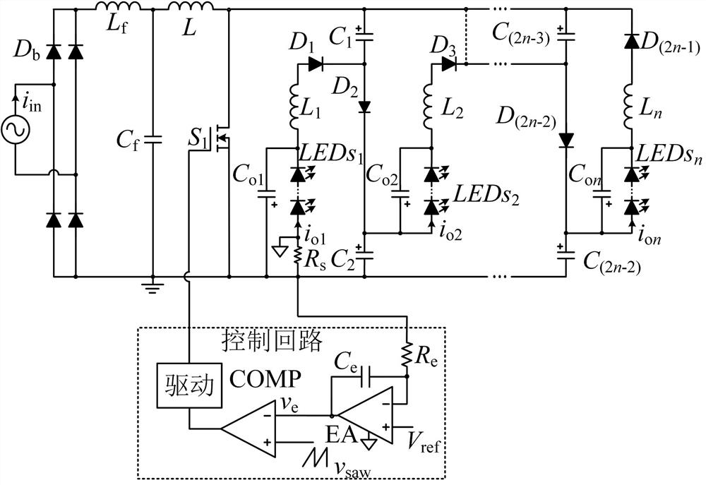
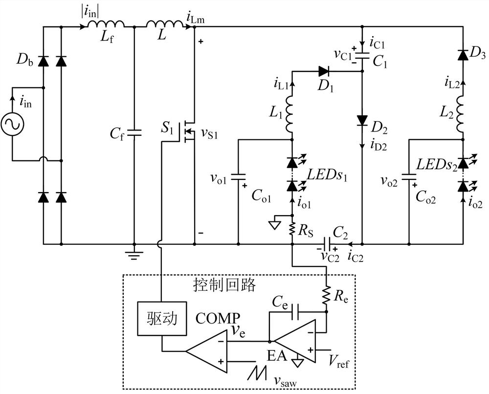
[0054] A low output ripple power factor correction converter of the present invention includes a rectifier bridge, a filter, a BuckPFC converter, a DC-DC converter in a subsequent stage, and a control circuit thereof. Such as Figure 6 As shown, the transformer T is equivalent to the excitation inductance L m , ideal transformer and leakage inductance L r form. 1: n is the number of turns on the primary side of the transformer compared to the number of turns on the secondary side. By sharing the active switch S 1 The Buck type PFC converter is integrated with the subsequent DC-DC converter. The Buck type PFC converter consists of a diode ( D B1 , D B2 and D B3 ),inductance L B ,capacitance C B and active switch S 1 composition. The DC-DC converter consists of a diode ( D o1 and D o2 ), resonant capa...


PUM


Abstract

The invention discloses a low-output ripple power factor correction converter which specifically comprises a rectifier bridge, a filter, a Buck PFC converter, a post-stage DC-DC converter and a control circuit thereof. The filter is composed of Lf and Cf; a transformer is allowed to be equivalent to an excitation inductor, an ideal transformer and a leakage inductor; the Buck PFC converter and thepost-stage DC-DC converter are integrated together by sharing an active switch; the Buck PFC converter is composed of a diode, an inductor, a capacitor and an active switch. The DC-DC converter is composed of a diode, a resonant capacitor, an output capacitor, a transformer, an active switch and an energy storage capacitor. The converter has the advantages of high efficiency, high power factor, low output ripple and the like, and is easy to expand into multi-path output. In addition, the converter is of an isolation structure and is safer.

Description

technical field [0001] The invention belongs to the technical field of converters, in particular to a low output ripple power factor correction converter. Background technique [0002] Power factor correction (power factor correction, PFC) converters are widely used to reduce input current distortion and meet related harmonic standards. In order to reduce the impact of power electronic equipment on the power quality of the power grid, the international IEC61000-3-2 Class C and the national harmonic standard GB / T 14549-1993 "Power Quality Harmonics in Public Power Grids" regulate the PF (Power factor) of power electronic equipment. , power factor) have strict requirements. Therefore, it is of great significance to adopt an LED driver with PFC function. [0003] Generally, PFC converters can be divided into single-stage, two-stage and quasi-single-stage structures. The main advantages of the single-stage structure are high efficiency and small size. However, no matter what ...

Claims


Application Information

Patent Timeline
IPC IPC(8): H02M1/42H02M3/156H02M3/335H02M7/217H02M1/14H05B45/355H05B45/36H05B45/375H05B45/382H05B45/3725
CPCH02M1/14H02M1/42H02M1/4241H02M3/156H02M3/33561H02M3/33569H02M7/217H05B45/355H05B45/36H05B45/3725H05B45/375H05B45/382H02M1/0038H02M1/0067H02M1/009Y02B20/30Y02B70/10
Inventor 贺明智曹克煜刘雪山史旭刘天成文娅孟鑫王学庆周述晗周群徐航
Owner SICHUAN UNIV
Learn More