[0005] The purpose of the present invention is to provide a UHMWPE pipe molding
system and molding process, to solve the above-mentioned background technology. In the actual transportation process, it is easy to cause the cavity to be unable to be filled due to the agglomeration of raw materials, resulting in a large space between the conveyed materials, resulting in insufficient material conveyed to the forming area, and resulting in a forming gap between the
sizing sleeve and the
sizing mandrel. Can not be fully filled, resulting in defects in the pipe forming body, thereby reducing the quality of the pipe forming
[0008] When working, in the prior art, during the process of screw conveying and forming the forming raw materials of pipes, the conveying cavity on the
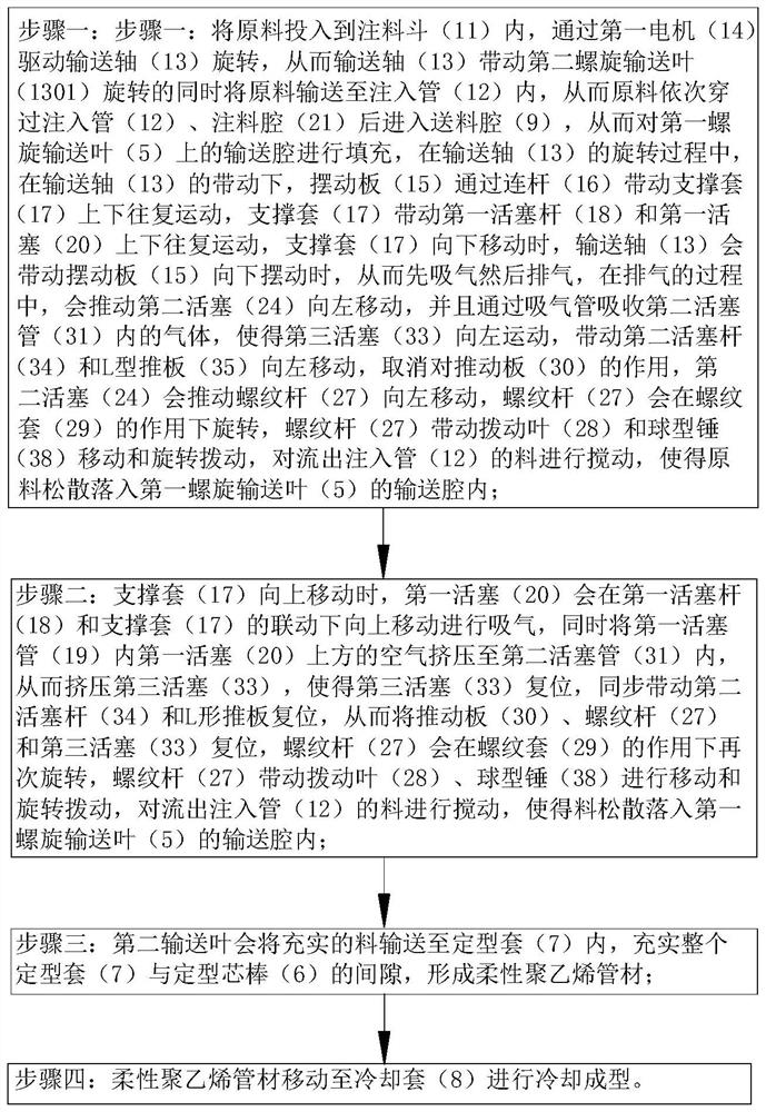
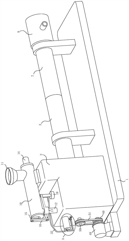
spiral blade is likely to be unable to fill the cavity due to the agglomeration of raw materials during the actual transportation process, resulting in a large gap between the conveyed materials. Due to the large space, the material transported to the forming area is not sufficient, and the forming gap between the shaping sleeve and the shaping mandrel cannot be completely filled, resulting in defects in the formed body of the pipe fittings, thereby reducing the quality of the pipe fittings. This technical solution solves the problem. The above problems, the specific working principle is as follows, the raw materials are put into the injection hopper, and the first motor drives the conveying shaft to rotate, so that the conveying shaft drives the second screw conveying blade to rotate and at the same time conveys the raw materials into the injection pipe, so that the raw materials pass through the injection pipe in turn. After the pipe and the injection chamber enter the feeding chamber, the conveying chamber on the first screw conveying leaf is filled. During the rotation of the conveying shaft, the swing plate drives the support sleeve to reciprocate up and down through the connecting rod, and the support sleeve drives the first
piston. The rod and the first
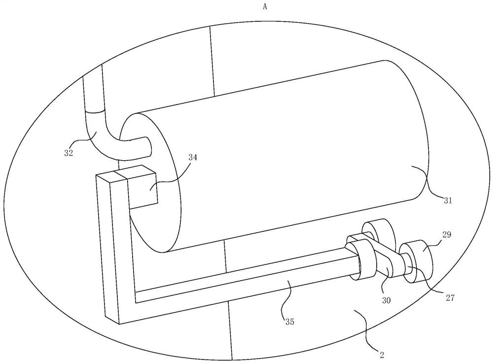
piston reciprocate up and down. When the support sleeve moves down, the conveying shaft will drive the swing plate to swing down, so that it first inhales and then exhausts. During the exhaust process, it will push the second piston to move to the left. , and absorb the gas in the second piston tube through the suction pipe, so that the third piston moves to the left, driving the second
piston rod and the L-shaped push plate to move to the left, canceling the effect on the push plate, and the second piston will push the
threaded rod Moving to the left, the
threaded rod will rotate under the action of the threaded sleeve, and the
threaded rod will drive the moving blade to move and rotate to stir the material flowing out of the injection pipe, so that the
raw material will loosely fall into the conveying chamber of the first screw conveying leaf , when the first piston moves to not seal the gas injection pipe, the gas that continues to be discharged will be injected into the annular
nozzle, and the gas vibration will be performed on the material accumulated below, so that the material can be fully filled in the conveying cavity of the first screw conveying leaf; the support sleeve When moving upward, the first piston will move upward under the linkage of the first
piston rod and the support sleeve to inhale air, and at the same time squeeze the air above the first piston in the first piston tube into the second piston tube, thereby squeezing the third piston tube. The piston makes the third piston reset, synchronously drives the second
piston rod and the L-shaped push plate to reset, thereby resets the push plate, threaded rod and the third piston, the threaded rod will rotate again under the action of the threaded sleeve, and the threaded rod drives the dial The movable blade moves and rotates to stir the material flowing out of the injection pipe, so that the material falls loosely into the conveying cavity of the first screw conveying leaf; The gap between the entire shaping sleeve and the shaping mandrel forms a flexible polyethylene pipe, and the flexible polyethylene pipe moves to the cooling jacket for cooling and forming; during the rotation of the conveying shaft in the present invention, the swing plate drives the supporting sleeve to reciprocate up and down through the connecting rod, The support sleeve drives the first piston rod and the first piston to reciprocate up and down. When the support sleeve moves downward, the conveying shaft will drive the swing plate to swing downward, so that air is first inhaled and then exhausted. During the sequence of
inhalation and exhaust , the second piston will drive the threaded rod to reset and move to the left and then to the right, the threaded rod will rotate under the action of the threaded sleeve, and the threaded rod will drive the moving blade to move and rotate to stir the material flowing out of the injection pipe. Make the material loosely fall into the conveying cavity of the first screw conveying blade, and in the process of exhausting, when the first piston moves to not seal the gas injection pipe, the gas that continues to be discharged will be injected into the annular
nozzle, and the accumulation below The material is subjected to gas vibration to make the material as full as possible in the conveying cavity of the first screw conveying leaf, and the second conveying leaf will convey the sufficient material to the shaping sleeve to fill the gap between the entire shaping sleeve and the shaping mandrel to ensure the shape of the formed pipe.
Processing quality


