A continuous carbonization furnace flue gas purification system

A flue gas purification system, carbonization furnace technology, applied in coke ovens, special forms of dry distillation, biofuels, etc., can solve the problems of dust rising again, easy gas leakage, low dust removal efficiency, etc., to improve efficiency and avoid leakage. Air and avoid noise pollution effect

Active Publication Date: 2022-01-25
深圳芯闻科技有限公司
View PDF0 Cites 0 Cited by
  • Summary
  • Abstract
  • Description
  • Claims
  • Application Information

AI Technical Summary

Problems solved by technology

[0003] 1. The ash unloading device at the bottom of the cyclone dust collector adopts a mechanical structure. Such a structural design is prone to air leakage, and the bottom of the cyclone dust collector itself is a negative pressure area. Once air leakage occurs, it will make The outside air enters the dust collector, which affects the effect of dust removal and causes dust confusion;
[0004] 2. Since the diameter of the bottom of the cyclone dust collector becomes smaller and the dust accumulates more, it is easy to cause the dust to be raised again between the inner and outer swirl layers. It is easy for the dust to be discharged with the ascending cyclone, resulting in a large amount of dust in the gas after dust removal, and the dust removal efficiency is low;
[0005] 3. It is necessary to cut off the air to ensure stability during the ash unloading process, and the dust in the ash unloading device is easily affected by the cyclone and flips up and down, so that the treatment of the dust cannot achieve good results. At the same time, the ash unloading device will open Causes a lot of noise interference, which is not conducive to production and environmental protection

Method used


Image

  • A continuous carbonization furnace flue gas purification system
  • A continuous carbonization furnace flue gas purification system
  • A continuous carbonization furnace flue gas purification system

Examples


Embodiment Construction

[0025] The following will clearly and completely describe the technical solutions in the embodiments of the present invention with reference to the accompanying drawings in the embodiments of the present invention. Obviously, the described embodiments are only some, not all, embodiments of the present invention. Based on the embodiments of the present invention, all other embodiments obtained by persons of ordinary skill in the art without making creative efforts belong to the protection scope of the present invention.

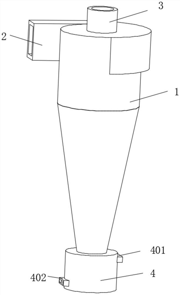
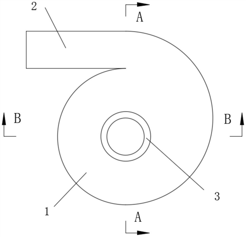
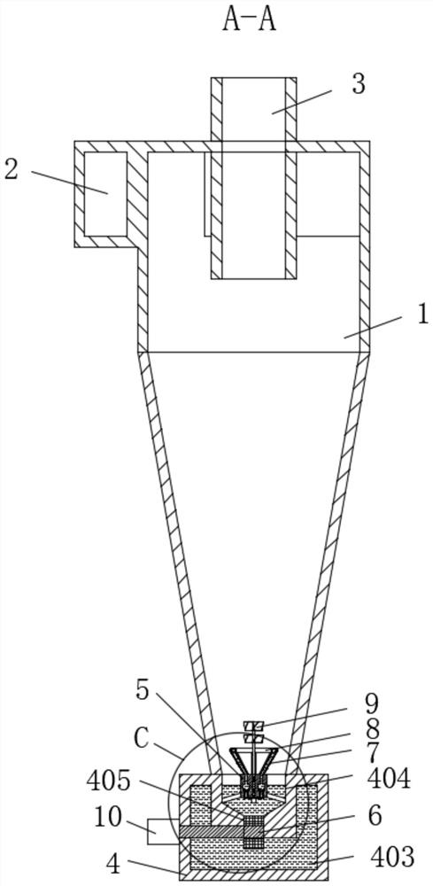
[0026] see Figure 1-7 , a continuous carbonization furnace flue gas purification system, including a shell 1, a tangential spiral air inlet 2 is opened on the back of the top of the shell 1, an air outlet 3 is opened in the middle of the top surface of the shell 1, and the shell 1 The bottom of the ash unloading device 4 is fixedly installed, the top of one side of the ash unloading device 4 is provided with a liquid inlet 401, and the bottom of the other sid...


PUM


Abstract

The invention relates to the field of environmental protection and dust removal technology, and discloses a casing, the back of the top of the casing is provided with a tangential spiral air inlet, the middle of the top surface of the casing is provided with an air outlet, and the bottom of the casing is fixedly installed with a dust discharge device, the top of the connection between the ash unloading device and the shell is provided with an ash collection tank, and the bottom inside the ash unloading device is provided with a liquid storage tank, and the ash unloading device is located between the liquid storage tank and the ash collection tank There is an exchange chute in the middle, the top of the ash collection chute is fixed with a hydraulic device through a connecting rod, and a turntable is installed on the inner side of the exchange chute, and evenly divided fan-shaped slots are opened on the disc of the turntable , through the inside of the ash unloading device, there are ash collection tanks and liquid storage tanks, and a turntable with fan-shaped slots is set between them. A hydraulic device is installed on the top of the ash collection tank, and it is equipped with a support guide rod, a liquid spray ring, and a movable column. The effect and efficiency of dust removal are improved, and the ash unloading is convenient and without interference.

Description

technical field [0001] The invention relates to the technical field of environmental protection and dust removal, in particular to a continuous carbonization furnace flue gas purification system. Background technique [0002] The carbonization furnace is a device that carbonizes wood chips, rice husks, and plant straws under high temperature conditions in the furnace. In order to improve efficiency and reduce pollution, the continuous type is now mostly used, that is, the gas generated by the first carbonization is recovered and purified, and then recycled and burned again. Therefore, whether it is recycled or discharged into the atmosphere, purification treatment is required. Purification requires desulfurization and dehydrogenation through a spray tower, and dust removal through a dust collector. Generally, a cyclone dust collector is used to improve the efficiency of dust removal. The first-stage dust removal is carried out through the bag filter for secondary filtration ...

Claims


Application Information

Patent Timeline
Patent Type & Authority Patents(China)
IPC IPC(8): C10B53/02
CPCC10B53/02Y02E50/10
Inventor 刘梦浩
Owner 深圳芯闻科技有限公司
Why Eureka
Try Eureka