Wet garbage disposal device

A technology of waste treatment device and anaerobic tank, which is applied in biomass post-treatment, biomass pre-treatment, biochemical cleaning device, etc. Property loss and other problems, to achieve the effect of improving the generation rate, improving the utilization rate, and high degree of automation

Pending Publication Date: 2021-02-19
杨淑桃
View PDF0 Cites 2 Cited by
  • Summary
  • Abstract
  • Description
  • Claims
  • Application Information

AI Technical Summary

Problems solved by technology

However, because anaerobic fermentation needs to be carried out in a sealed environment, wet garbage is mostly in a static state in anaerobic tanks, resulting in uneven distribution of anaerobic bacteria in it, and the fermentation rate needs to be improved; even if some anaerobic tanks are equipped with Stirring device, the operation of these stirring devices consumes electric energy, which increases the power consumption of the processing device, and when the electrical equipment is working, it is easy to generate electric sparks. and property damage

Method used


Image

  • Wet garbage disposal device
  • Wet garbage disposal device
  • Wet garbage disposal device

Examples


Embodiment 1

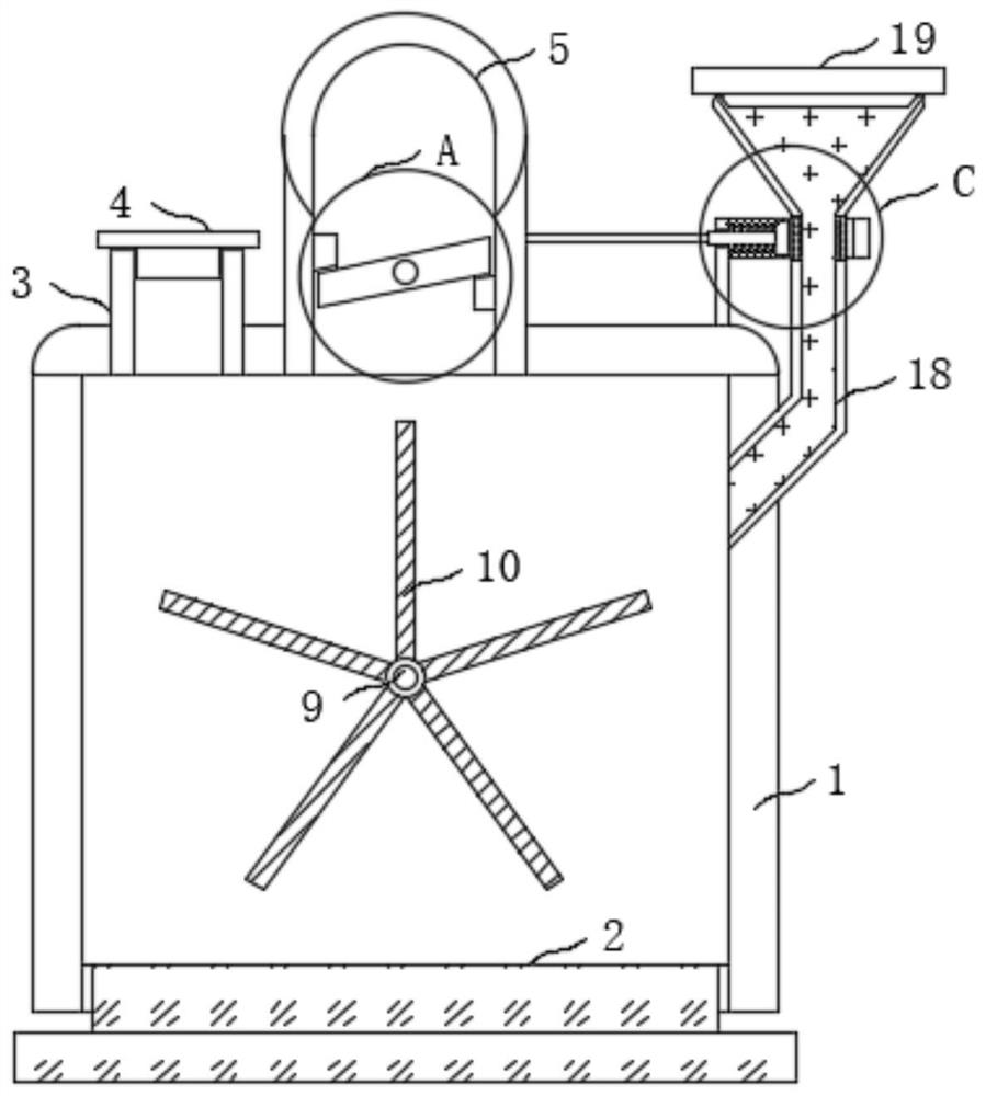
[0026] refer to Figure 1-4 , a wet garbage treatment device, including a sealing base 2 installed on an anaerobic tank 1, a feed seat 3 and a biogas discharge square pipe 5 are fixedly installed on the anaerobic tank 1, and a sealing plate is threaded on the feed seat 3 4;

[0027] Of note above are:

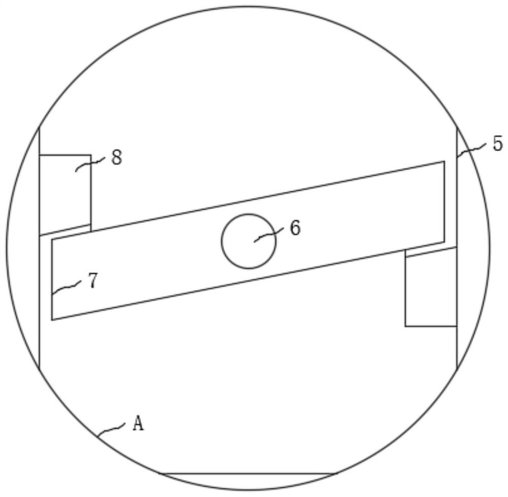
[0028] 1. A baffle 7 is connected to the biogas discharge square pipe 5 through the rotation of the rotating rod 6. A torsion spring is installed between the baffle 7 and the two ends of the biogas discharge square pipe 5. When the biogas generated in the anaerobic tank 1 is When it is small, due to the elastic force of the torsion spring, the position and angle of the baffle plate 7 in the biogas discharge square pipe 5 can be kept unchanged, and the biogas discharge square pipe 5 is kept in a sealed state.

[0029] 2. There are two magnetic blocks 8 fixedly installed in the biogas discharge square pipe 5, and the two magnetic blocks 8 are attached to the left upper end and ...

Embodiment 2

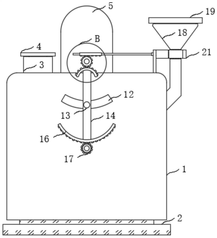
[0038] refer to figure 1 , figure 2 , Figure 4 , Figure 5 , the difference between embodiment two and embodiment one is: an additive feed hopper 18 is fixed in the shape of a rod on the anaerobic tank 1, and the additive feed hopper 18 is threadedly connected with a dust cover 19, and on the anaerobic tank 1 A support rod 20 is fixedly installed on the support rod 20, and a positioning frame 21 matched with the additive feed hopper 18 is fixedly installed on the support rod 20. One end of the positioning frame 21 close to the support rod 20 is slidably connected with a push rod 22, and the push rod 22 is fixedly installed. There is a push block 23, a rubber hose 24 corresponding to the position of the push block 23 is fixedly installed on the additive feed hopper 18, a spring 25 is installed between the push block 23 and the positioning frame 21, and a push rod 22 and the driving gear 11 Installed with an opening mechanism;

[0039] The opening mechanism is made up of chu...


PUM


Abstract

The invention discloses a wet garbage disposal device, which comprises a sealing base installed on an anaerobic jar, wherein the anaerobic jar is fixedly provided with a material feeding seat and a biogas discharging square tube; the material feeding seat is in threaded connection with a sealing plate; and in the biogas discharging square tube, a baffle plate is rotatably connected through a rotary rod. The wet garbage disposal device has the advantages that the wet garbage disposal device can utilize biogas to generate air pressure to enable stirring vanes to automatically rotate to stir wetgarbage in a process that the biogas is generated for wet garbage in the anaerobic jar, a certain quantity of urea is automatically added into the anaerobic jar, a biogas generation rate is improved,and a use ratio of a biogas fermentation substrate and the content of methane in biogas can be effectively improved. In addition, in a whole process, manual control is not required, an automation degree is high, electrical equipment does not need to be used for carrying out driving, the device is free from operation power consumption, the problem of biogas explosion caused by electric sparks can be avoided, and a safety coefficient is high.

Description

technical field [0001] The invention relates to the technical field of garbage treatment, in particular to a wet garbage treatment device. Background technique [0002] As people's awareness of environmental protection becomes more and more sound, the reasonable disposal of garbage has received widespread attention. In order to facilitate the follow-up treatment of garbage, it will be divided into two categories: dry garbage and wet garbage. [0003] In the prior art, a more reasonable and effective treatment method for wet garbage is: put the screened wet garbage into an anaerobic tank for fermentation treatment, and the generated biogas is used for power generation. However, because anaerobic fermentation needs to be carried out in a sealed environment, wet garbage is mostly in a static state in anaerobic tanks, resulting in uneven distribution of anaerobic bacteria in it, and the fermentation rate needs to be improved; even if some anaerobic tanks are equipped with Stirr...

Claims


Application Information

Patent Timeline
Patent Type & Authority Applications(China)
IPC IPC(8): C12M1/107C12M1/02C12M1/00
CPCC12M21/04C12M23/38C12M23/48C12M27/02C12M37/04
Inventor 杨淑桃
Owner 杨淑桃
Why Eureka
Try Eureka