Resistance device for steel pipe pile

A technology of resistance device and steel pipe pile, which is applied in the direction of sheet pile wall, building, foundation structure engineering, etc., can solve the problems of unfavorable vertical bearing capacity of steel pipe pile, heavy welding workload, and prone to hammering, etc., to avoid The effect of material cost and on-site workload, less structural consumables, and increased contact area

Inactive Publication Date: 2021-02-19
OFFSHORE OIL ENG CO LTD
View PDF6 Cites 3 Cited by
  • Summary
  • Abstract
  • Description
  • Claims
  • Application Information

AI Technical Summary

Problems solved by technology

[0005] (2) Among the measures to improve the penetration resistance, closed-end piles are completely closed at the pile end, so the driving resistance is high, and hammering is easy to occur, and the soil around the pile is greatly disturbed, and the soil bearing capacity needs a longer recovery time; The size design of the sealing plate and the annular sealing plate requires accurate geological survey results, and at the same time reduces the influx of soil during the penetration process, which is unfavorable to the vertical bearing capacity of the steel pipe pile; adding a vertical partition at the end of the pile is usually mostly Cross-vertical arrangement does not significantly increase the penetration resistance, and the welding workload is large and difficult to weld; when the pile end is completely closed, it is difficult to evaluate the penetration, and it is difficult to define the location of the soil plugging condition. For steel pipe piles that are flush with the surface, the penetration resistance will increase greatly after the soil plug inside the pile is uplifted.

Method used


Image

  • Resistance device for steel pipe pile
  • Resistance device for steel pipe pile

Examples


Embodiment Construction

[0026] The present invention will be further described below in conjunction with the accompanying drawings and specific embodiments, so that those skilled in the art can better understand the present invention and implement it, but the examples given are not intended to limit the present invention.

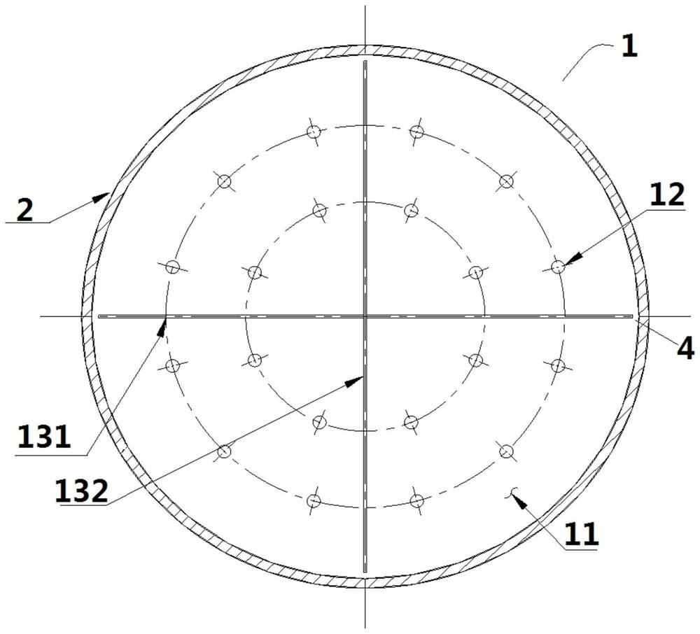
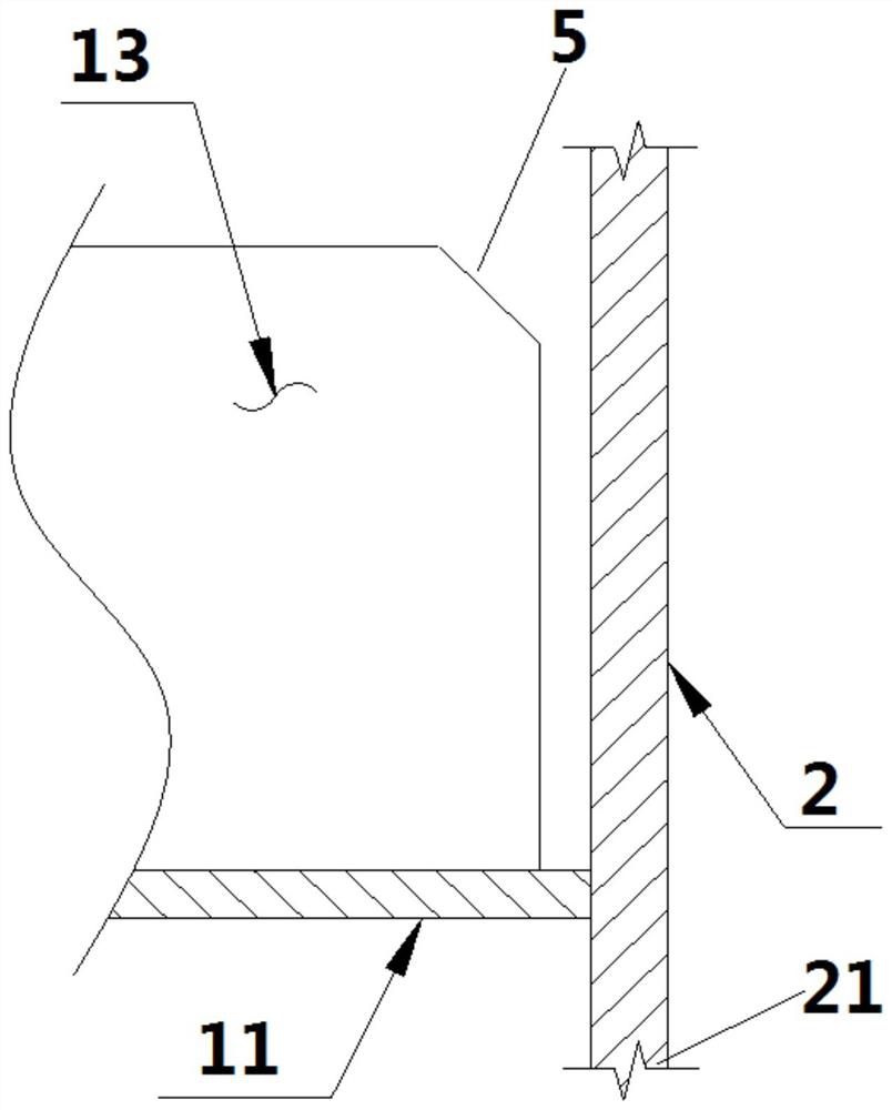
[0027] figure 1 is a schematic diagram of the installation of the resistance device for steel pipe piles of the present invention, figure 2 is a structural schematic diagram of the resistance device for steel pipe piles of the present invention, as figure 1 and figure 2 As shown, a resistance device 1 for a steel pipe pile 2 includes a circular sealing plate 11, the sealing plate 11 is fixed in the steel pipe pile 2, and is close to the pile end 21 of the steel pipe pile 2 driven into weak soil, and the sealing The plate 11 is perpendicular to the inner wall of the steel pipe pile 2. The diameter of the sealing plate 11 is equal to or close to the inner diameter of the steel p...


PUM


Abstract

The invention discloses a resistance device for a steel pipe pile. The resistance device comprises a circular sealing plate and a plurality of through holes formed in the sealing plate at intervals. The sealing plate is fixed in the steel pipe pile and close to the pile end of the steel pipe pile. The sealing plate is perpendicular to the inner wall of the steel pipe pile. The sealing plate sealsthe steel pipe pile. The reserved through holes are used for draining water and preventing excessive soil from inrushing into the steel pipe pile. The sealing plate is fixed to the position away fromthe pile end by a preset distance. The contact area between the steel pipe pile and soil can be increased in the pile driving process, and therefore the penetration resistance of the steel pipe pile in the soil driving process is increased through water pressure or soil pressure applied to the sealing plate. The anti-slip effect can be effectively achieved when a soft soil environment exists in the mud penetration depth range. According to the resistance device for the steel pipe pile, the structural consumables of the structure are few, and excessive extra material cost and field workload canbe avoided while the penetration resistance of the steel pipe pile is improved and the bearing capacity safety is guaranteed.

Description

technical field [0001] The invention relates to steel pipe piles in the field of marine engineering, and is a resistance device for steel pipe piles. Background technique [0002] At present, the prevention of sliding piles in marine engineering is mainly considered from the following two aspects: reducing the hammering energy and reducing the downward load; increasing the penetration resistance during the driving process of steel pipe piles. Reduce hammering energy: reduce the risk of slipping piles by replacing small-energy hammer clicks; increase penetration resistance: (1) closed piles, (2) increase ring-shaped sealing plates at pile ends; (3) increase vertical Partition; (4) The pile end is completely closed. [0003] There is following problem in above-mentioned anti-slip pile measure: [0004] (1) Sliding piles usually occur when the pile foundation penetrates from sandy soil or hard clay layer to the soil layer where the resistance of the pile end suddenly decrease...

Claims


Application Information

Patent Timeline
Patent Type & Authority Applications(China)
IPC IPC(8): E02D5/28
CPCE02D5/285
Inventor 王江宏曹竞祎刘玉玺黄怀州徐峰侯涛刘洪涛张孝卫
Owner OFFSHORE OIL ENG CO LTD
Why Eureka
Try Eureka