
Boiler flue gas waste heat recoverer and waste heat recovery method thereof

A waste heat recovery and boiler flue gas technology, applied in indirect heat exchangers, heat exchange equipment, climate sustainability, etc., can solve the problems of poor filtering effect, single heating effect, poor heating effect, etc., to avoid heat conduction efficiency Lower, easy to clean and replace the filter screen, increase the effect of filtering effect

Inactive Publication Date: 2021-02-19
河南省锅炉压力容器安全检测研究院
View PDF5 Cites 1 Cited by
  • Summary
  • Abstract
  • Description
  • Claims
  • Application Information

AI Technical Summary

Problems solved by technology

[0003] However, there is generally no dust removal device inside the existing boiler flue gas waste heat recovery device, which will cause the leftover flue gas dust to adhere to the inner wall of the recovery device after the flue gas passes through. If it is not cleaned for a long time, it will be difficult to clean and affect the heating efficiency;
[0004] And when filtering the dust in the flue gas, it is only filtered once, resulting in poor filtering effect, and a lot of dust will enter the interior of the recycler, resulting in poor heating effect, and it is not easy to replace the filter screen, and the heating effect of the existing waste heat recovery method Single, and it will cause poor heating effect after long-term use

Method used


Image

  • Boiler flue gas waste heat recoverer and waste heat recovery method thereof
  • Boiler flue gas waste heat recoverer and waste heat recovery method thereof
  • Boiler flue gas waste heat recoverer and waste heat recovery method thereof

Examples


Embodiment Construction

[0030] The following will clearly and completely describe the technical solutions in the embodiments of the present invention with reference to the accompanying drawings in the embodiments of the present invention. Obviously, the described embodiments are only some, not all, embodiments of the present invention. Based on the embodiments of the present invention, all other embodiments obtained by persons of ordinary skill in the art without making creative efforts belong to the protection scope of the present invention.

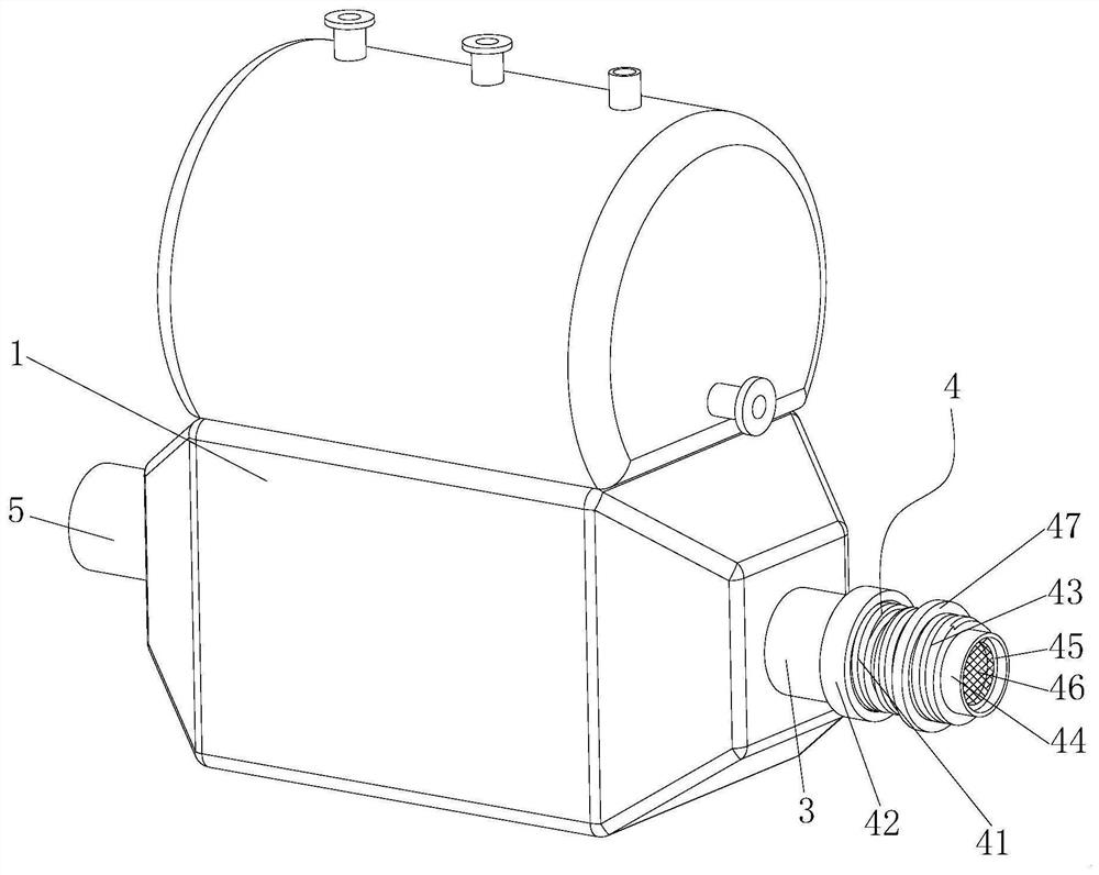
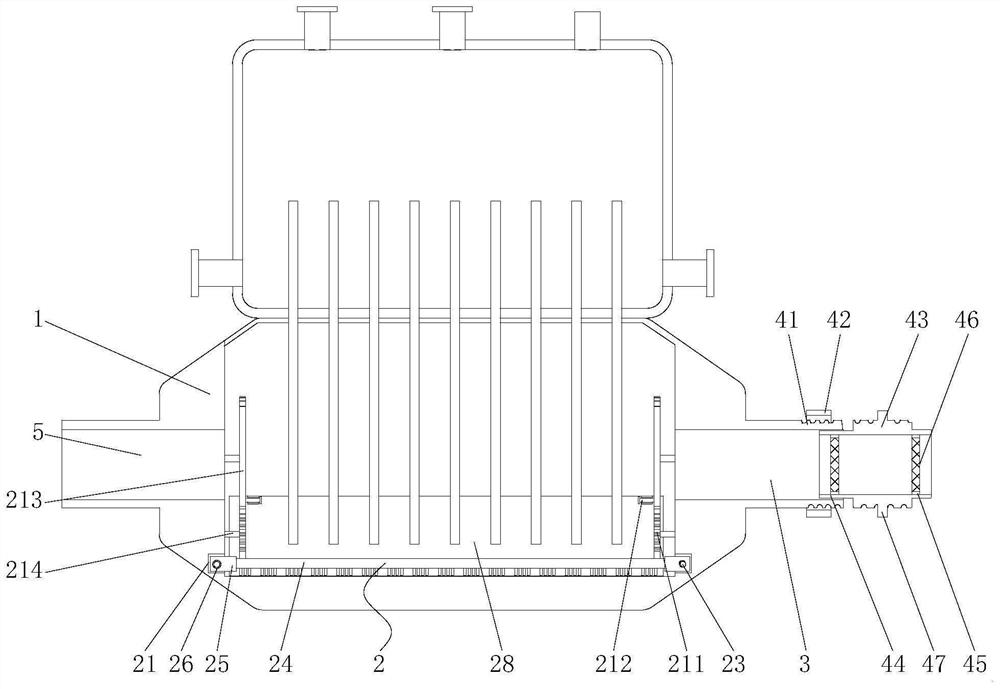
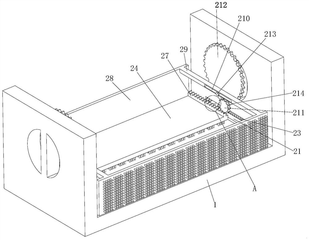
[0031] see Figure 1-5 , the present invention provides a technical solution: a boiler flue gas waste heat recovery device, including a recovery device body 1, a cleaning assembly 2 is fixed inside one side of the recovery device body 1, and a side surface of the recovery device body 1 A smoke inlet pipe 3 is connected through it, and a filter assembly 4 is fixed inside one side of the smoke inlet pipe 3;

[0032] The cleaning assembly 2 includes a first dust...


PUM


Abstract

The invention discloses a boiler flue gas waste heat recoverer and a waste heat recovery method thereof. The boiler flue gas waste heat recoverer comprises a recoverer main body, wherein a cleaning assembly is fixed inside one side of the recoverer main body, a smoke inlet pipe is connected to the side face of one side of the recoverer main body in a penetrating mode, and a filtering assembly is fixed inside one side of the smoke inlet pipe; and the cleaning assembly comprises a first dust removal plate installed inside the bottom end of one side of the recoverer main body, sliding blocks arewelded and fixed to the middles of the plate surfaces of the two sides of the first dust removal plate, and rotating grooves are formed in the positions, corresponding to the sliding blocks, of the side faces of the two sides of the interior of the recoverer main body. According to the boiler flue gas waste heat recoverer and the waste heat recovery method thereof, a cleaning device is adopted, sothat the cleaning efficiency can be improved, and the situation that the heat conduction efficiency is reduced due to excessive dust, and then the heating effect is poor is avoided; the filtering device is further adopted, so that the dust can be filtered through double filtration, the filtering effect is improved, and a filter screen can be conveniently cleaned and replaced; and the waste heat recovery method has various effects, and the long-time heating effect is facilitated.

Description

technical field [0001] The invention belongs to the technical field of heating equipment, in particular to a boiler flue gas waste heat recovery device and a waste heat recovery method. Background technique [0002] Flue gas waste heat recovery is mainly to convert the heat carried by the flue gas into usable heat through a certain heat exchange method, and the heat pipe waste heat recovery device is a special equipment for coal-fired, oil-fired, and gas-fired boilers. It is installed at the boiler smoke port to recover the flue gas Waste heat is used to heat domestic water or make up water for the boiler; the lower part is the flue, the upper part is the water tank, and there is a partition in the middle; The flue of the waste heat return device of the heat pipe scours the lower end of the heat pipe. [0003] However, there is generally no dust removal device inside the existing boiler flue gas waste heat recovery device, which will cause the leftover flue gas dust to adhe...

Claims


Application Information

Patent Timeline
IPC IPC(8): F28D15/02F28F19/01F28G1/00F28G15/06F23J15/02F23J15/06
CPCF23J15/025F23J15/06F28D15/0275F28F19/01F28G1/00F28G15/06Y02E20/30
Inventor 金璐桑山松杨伟冯艳丽李永赞李志敏刘新尚张阳耿广威陈会丽张文雅宋传静胡学锋赵中华薛冰李明强郭成立霍华亮王辉戴莹莹刘元武献峰
Owner 河南省锅炉压力容器安全检测研究院
Learn More