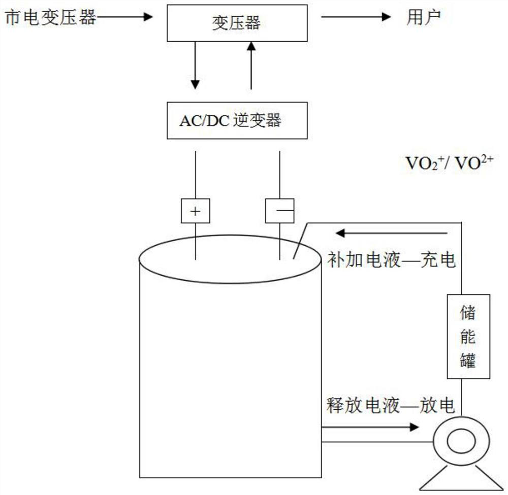
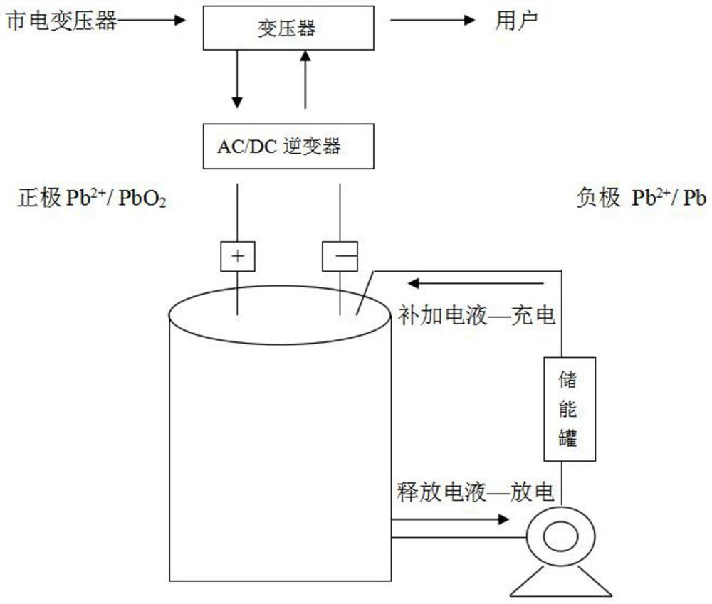
Lead-acid flow battery
A liquid flow battery and lead-acid technology, applied in the direction of fuel cells, regenerative fuel cells, circuits, etc., can solve problems that have not been involved in the research and development of energy storage devices, and achieve the effects of reducing hydrogen evolution during charging, increasing electrode potential, and being easy to control
- Summary
- Abstract
- Description
- Claims
- Application Information
AI Technical Summary
Problems solved by technology
Method used
Image

Examples
Embodiment example 1
[0023] 1. Substrate preparation:
[0024] Mix carbon powder and high-density polyethylene with a mass ratio of 6:1, and press it into a substrate.
[0025] 2. Positive plate preparation:
[0026] At a pressure of 8kg / cm 2 , at a temperature of 160 to 180°C, press-bond glassy carbon on the substrate, add 0.1% Bi 3+ and 0.5% Ni 2 or soluble salt as a catalyst to form the positive plate.
[0027] 3. Negative plate preparation:
[0028] At a pressure of 8kg / cm 2 , under the condition that the temperature is 160 to 180 DEG C, compound a nickel foam layer on the substrate, and add 0.2% sodium lignosulfonate to form a negative plate.
[0029] 3. Equipped with electrolyte:
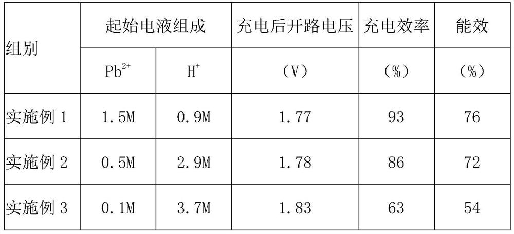
[0030] 1.5mol / LPb(CH 3 SO 3 ) 2 and 0.9mol / LCH 3 SO 3 The electrolyte composed of H is fully mixed and then 10mmol / L of C is added 16 h 33 (CH 3 )N + Electrolyte additive.
[0031] 4. Battery charge and discharge current density control:
[0032] The electro-hydraulic flow rate of battery charge ...
Embodiment example 2
[0034] 1. Substrate preparation:
[0035] Mix carbon powder and high-density polyethylene with a mass ratio of 6:1, and press it into a substrate.
[0036] 2. Positive plate preparation:
[0037] At a pressure of 8kg / cm 2 , at a temperature of 160 to 180°C, press-bond glassy carbon on the substrate, add 0.2% Bi 3+ and 0.5% Ni 2 or soluble salt as a catalyst to form the positive plate.
[0038] 3. Negative plate preparation:
[0039] At a pressure of 8kg / cm 2 , under the condition that the temperature is 160 to 180 DEG C, compound a nickel foam layer on the substrate, and add 0.3% sodium lignosulfonate to form a negative plate.
[0040] 3. Equipped with electrolyte:
[0041] 0.5mol / LPb(CH 3 SO 3 ) 2 and 2.9mol / LCH 3 SO 3 The H composition electrolyte is thoroughly mixed.
[0042] 4. Battery charge and discharge current density control:
[0043] The electro-hydraulic flow rate of battery charge and discharge is controlled at 3mA / cm 2 , The charging and discharging...
Embodiment example 3
[0046] 1. Substrate preparation:
[0047] Mix carbon powder and high-density polyethylene with a mass ratio of 6:1, and press it into a substrate.
[0048] 2. Positive plate preparation:
[0049] At a pressure of 8kg / cm 2 , at a temperature of 160 to 180°C, press-bond glassy carbon on the substrate, add 0.2% Bi 3+ and 0.5% Ni 2 or soluble salt as a catalyst to form the positive plate.
[0050] 3. Negative plate preparation:
[0051] At a pressure of 8kg / cm 2 , under the condition that the temperature is 160 to 180 DEG C, compound a nickel foam layer on the substrate, and add 0.3% sodium lignosulfonate to form a negative plate.
[0052] 3. Equipped with electrolyte:
[0053] 0.1mol / LPb(CH 3 SO 3 ) 2 and 3.7mol / LCH 3 SO 3 The H composition electrolyte is thoroughly mixed. 4. Battery charge and discharge current density control:
[0054] The electro-hydraulic flow rate of battery charge and discharge is controlled at 1mA / cm 2 , The charging and discharging efficiency...
PUM
 Abstract
Description
Claims
Application Information
 - R&D Engineer
- R&D Manager
- IP Professional
- Industry Leading Data Capabilities
- Powerful AI technology
- Patent DNA Extraction
Browse by: Latest US Patents, China's latest patents, Technical Efficacy Thesaurus, Application Domain, Technology Topic.
© 2024 PatSnap. All rights reserved.Legal|Privacy policy|Modern Slavery Act Transparency Statement|Sitemap