Waste gas treatment device for metallurgy

A waste gas treatment device and waste residue technology, which is applied in gas treatment, combined devices, filter circuits, etc., can solve problems such as device damage, imperfect functions, and endangering the health of staff, and achieve the effect of solving equipment damage and facilitating collection

Pending Publication Date: 2021-02-26
JIANGSU FEILU HEAVY MACHINERY MFG CO LTD
View PDF0 Cites 0 Cited by
  • Summary
  • Abstract
  • Description
  • Claims
  • Application Information

AI Technical Summary

Problems solved by technology

[0003] Metallurgical waste gas is mainly composed of nitrogen oxide particles, sulfur oxide particles and some heavy metal particles. There are also a large number of gaseous sulfides, nitrides and non-metallic particles. The composition of flue gas and dust is complex. If the metallurgical waste gas is not treated If it is discharged, it will not only pollute the environment, but also pose a threat to human health. When metallurgical factories are working, there will be a lot of waste gas, and the direct discharge of waste gas will pollute the surrounding environment and affect the health of people around.
[0004] At present, the existing waste gas treatment devices have the following deficiencies: 1. The functions are not perfect enough to fully treat the waste gas, which endangers the health of the staff; 2. Metal particles and dust will be produced during the metallurgical process, which enter the device with the waste gas 3. The metal particles contained in the exhaust gas are not easy to collect after treatment, and if they exist in the device for a long time, it may cause damage to the device; therefore, we make improvements and propose a A waste gas treatment device for metallurgy

Method used


Image

  • Waste gas treatment device for metallurgy
  • Waste gas treatment device for metallurgy
  • Waste gas treatment device for metallurgy

Examples


Embodiment

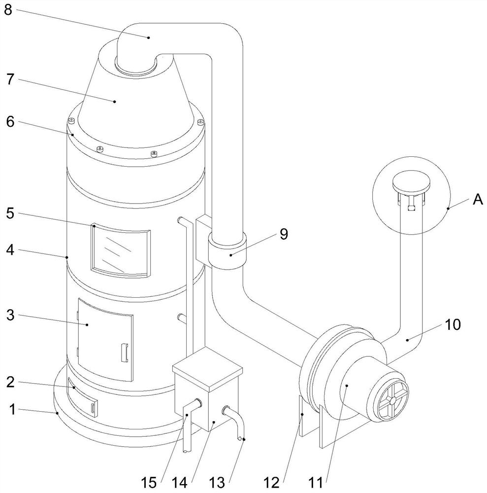
[0027] Example: such as figure 1 As shown, a waste gas treatment device for metallurgy of the present invention includes a cylinder body 4, a cover plate 6 is fixedly connected to the top of the cylinder body 4, an air outlet port 7 is fixedly connected to the top of the cover plate 6, and the inside of the air outlet port 7 is fixed An air outlet pipe 8 is connected, and a clamp 9 is fixedly connected to one side of the cylinder body 4. The air outlet pipe 8 is arranged inside the clamp 9. One end of the air outlet pipe 8 is fixedly connected to an exhaust fan 11, and the bottom of the exhaust fan 11 is fixedly connected to a The fixed frame 12, the exhaust pipe 10 is fixedly connected to the output end of the exhaust fan 11, the air inlet pipe 16 is fixedly connected to one side of the cylinder body 4, the motor compartment 20 is fixedly connected to one side of the cylinder body 4, and the bottom side of the cylinder body 4 is fixed A box body 14 is connected.

[0028] One...


PUM


Abstract

The invention discloses a waste gas treatment device for metallurgy. The waste gas treatment device comprises a barrel, a cover plate is fixedly connected to the top of the barrel, an air outlet connector is fixedly connected to the top of the cover plate, an air outlet pipe is fixedly connected to the interior of the air outlet connector, a hoop is fixedly connected to one side of the barrel, theair outlet pipe is arranged in the hoop, and an exhaust fan is fixedly connected to one end of the air outlet pipe; a fixing frame is fixedly connected to the bottom of the exhaust fan, an exhaust pipe is fixedly connected to the output end of the exhaust fan, an air inlet pipe is fixedly connected to one side of the barrel, a motor bin is fixedly connected to one side of the barrel, a box is fixedly connected to one side of the bottom of the barrel, and connecting blocks are fixedly connected to the two sides of the top in the barrel; and a filter plate and an activated carbon adsorption plate are arranged on the inner side of the connecting block, the filter plate is fixedly arranged below the activated carbon adsorption plate, and a servo motor is fixedly arranged in the motor bin. According to the waste gas treatment device for metallurgy, metal particles and dust cannot be discharged into air along with purified waste gas, and meanwhile, the metal particles are convenient to collect.

Description

technical field [0001] The invention relates to the technical field of waste gas treatment, in particular to a waste gas treatment device for metallurgy. Background technique [0002] Metallurgy is the process and technology of extracting metals or metal compounds from minerals, and using various processing methods to make metals into metal materials with certain properties. Metallurgy has a long history of development, from the Stone Age to the subsequent Bronze Age, and then to modern times. Large-scale development of iron and steel smelting. The history of human development incorporates the development history of metallurgy. Metallurgical technologies mainly include pyrometallurgy, hydrometallurgy and electrometallurgy. [0003] Metallurgical waste gas is mainly composed of nitrogen oxide particles, sulfur oxide particles and some heavy metal particles. There are also a large number of gaseous sulfides, nitrides and non-metallic particles. The composition of flue gas and...

Claims


Application Information

Patent Timeline
Patent Type & Authority Applications(China)
IPC IPC(8): B01D50/00B01D53/04B01D36/00
CPCB01D53/04B01D36/001B01D2253/102B01D2258/025B01D50/60
Inventor 张静张刚张晴宇
Owner JIANGSU FEILU HEAVY MACHINERY MFG CO LTD
Why Eureka
Try Eureka