
Auxiliary machining method for aviation thin-wall micro-structure part

An auxiliary processing, thin-walled technology, applied in metal processing equipment, metal processing mechanical parts, manufacturing tools, etc., can solve the problems of difficult to control the size of the burr on the bottom edge, weak rigidity of the thin-walled structure, and large size of the burr. , to achieve the effect of efficient cleaning and separation, low-efficiency material removal, and reduction of elastic deformation

Inactive Publication Date: 2021-02-26
CHONGQING UNIV +1
View PDF11 Cites 2 Cited by
  • Summary
  • Abstract
  • Description
  • Claims
  • Application Information

AI Technical Summary

Problems solved by technology

However, the structure size of the core parts of the instrument in the aviation field is small, the rigidity of the thin-walled structure is weak, and the size of the burr cut out during the micro-milling process is too large, resulting in the roughness of the processed surface of the thin-walled micro-structured parts, the accuracy of the structural size, and the size of the burr cut out of the bottom edge. uncontrollable
[0003] At present, there is still no suitable processing method to solve the above problems, so it is particularly important to propose an auxiliary processing method to improve the processing quality

Method used


Image

  • Auxiliary machining method for aviation thin-wall micro-structure part
  • Auxiliary machining method for aviation thin-wall micro-structure part
  • Auxiliary machining method for aviation thin-wall micro-structure part

Examples


Embodiment 1

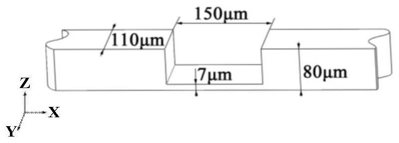
[0042] This embodiment discloses an auxiliary processing method for aerospace thin-walled microstructure parts, figure 1 It is the characteristic dimension diagram of aerospace thin-walled micro-structured part 1. It can be seen from the figure that the part will undergo elastic deformation in the Z and Y directions during the micro-milling process. First, the deformation of the aerospace thin-walled micro-structured part 1 during processing is calculated. Such as figure 2 As shown, if the thin-walled microstructure part 1 is simplified as a beam fixed at both ends, the deformation in different directions is calculated as:

[0043] (1) Deformation calculation in the Z direction

[0044] The redundant constraints are:

[0045]

[0046] The deformation boundary condition at the microstructure is:

[0047]

[0048] According to the solution of material mechanics, it can be known that the deflection W at any point on the section is:

[0049]

[0050] In formula (3),...

Embodiment 2

[0085] This embodiment provides a relatively basic implementation method, an auxiliary processing method for aerospace thin-walled microstructure parts, figure 1 It is the characteristic size diagram of aerospace thin-walled microstructure part 1. It can be seen from the diagram that the part will undergo elastic deformation in the Z and Y directions during the micro-milling process. First, the deformation of the aerospace thin-walled micro-structured part 1 during processing is calculated. Such as figure 2 As shown, if the thin-walled microstructure part 1 is simplified as a beam fixed at both ends, the deformation in different directions is calculated as:

[0086] (4) Deformation calculation in the Z direction

[0087] The redundant constraints are:

[0088]

[0089] The deformation boundary condition at the microstructure is:

[0090]

[0091] According to the solution of material mechanics, it can be known that the deflection W at any point on the section is:

...

Embodiment 3

[0123] The main steps of this embodiment are the same as those in Embodiment 2. Further, the vertical high-precision gauge block 2 and the horizontal high-precision gauge block 3 are both square, and the material is GCr15, which has high hardness, high thickness, high contact fatigue and uniform structure. Its modulus of elasticity is 219GPa, hardness is 25.8HRC, yield strength is 518.42MPa, and the precision is 0.


PUM

PropertyMeasurementUnit
Diameteraaaaaaaaaa
Elastic modulusaaaaaaaaaa
Yield strengthaaaaaaaaaa

Abstract

The invention discloses an auxiliary machining method for an aviation thin-wall microstructure part. The auxiliary machining method comprises the following steps: 1) positioning the aviation thin-wallmicrostructure part; 2) respectively applying pressure to two ends of the aviation thin-wall microstructure part by using two micro-diameter needle heads; 3) in the process that the two micro-diameter needle heads are used for applying pressure, the other micro-diameter needle head is used for dipping a trace amount of adhesive, and the trace amount of adhesive is made to make contact with a thin-neck inner base line of the aviation thin-wall microstructure part; 4) removing a vertical high-precision gauge block; 5) keeping the two micro-diameter needle heads to apply pressure to the two endsof the aviation thin-wall micro-structure part all the time until the trace amount of adhesive flows and is cured; and 6) observing the thickness of the trace amount of adhesive by adopting a magnifying lens to ensure that the thickness of the trace amount of adhesive is greater than the thickness of the microstructure, and the like. The machining process for the aviation thin-wall microstructurepart has the obvious auxiliary improvement effect, the operation process is clear, the method is simple and practical, and application and popularization of aviation instrument microstructure part machining are facilitated.

Description

technical field [0001] The invention belongs to the technical field of mechanical processing, and in particular relates to an auxiliary processing method for aviation thin-walled microstructure parts. Background technique [0002] The processing of the core parts (thin-walled micro-structured parts) of the instrument in the aviation field has strict requirements on the size error of the microstructure, the quality of the machined surface, and the size of the burr, so as to ensure that the aviation instrument has excellent accuracy indicators and service performance during the service process. In order to ensure high-efficiency and high-quality processing of core parts of aviation instruments, micro-milling processing technology is used as the main processing technology of microstructure. However, the structure size of the core parts of the instrument in the aviation field is small, the rigidity of the thin-walled structure is weak, and the size of the burr cut out during the...

Claims


Application Information

Patent Timeline
IPC IPC(8): B23C3/00B23Q3/18B23Q3/08
CPCB23C3/00B23Q3/18B23Q3/084B23Q2703/10
Inventor 渠达王波曹华军薛家岱伊浩张宸嘉
Owner CHONGQING UNIV
Learn More