Automatic argon blowing method and system of steel ladles

A ladle and automatic technology, applied in the field of steelmaking, to reduce labor intensity, save temperature measurement materials, and improve the quality of molten steel

Active Publication Date: 2021-02-26
WISDRI ENG & RES INC LTD
View PDF7 Cites 3 Cited by
  • Summary
  • Abstract
  • Description
  • Claims
  • Application Information

AI Technical Summary

Problems solved by technology

[0006] The present invention also provides a ladle automatic argon blowing system, including: a blowing control module, an argon blowing control module, a robot control module, an argon gas pipeline, a distance measuring module and a ladle moving module. The whole process of automatic argon blowing control before the ladle is placed on the continuous casting machine solves the problems existing in manual operation

Method used


Image

  • Automatic argon blowing method and system of steel ladles
  • Automatic argon blowing method and system of steel ladles

Examples


Embodiment 1

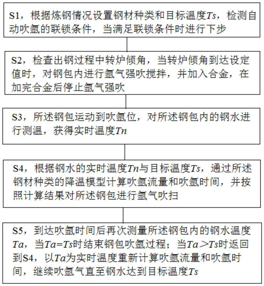
[0039] A method for automatically blowing argon in a ladle, refer to figure 1 , including the following steps:

[0040] S1, set the steel type and target temperature Ts according to the steelmaking situation, detect the interlocking conditions of automatic argon blowing, and tap the steel when the interlocking conditions are met;

[0041] S2, check the inclination angle of the converter during the tapping process, when the inclination angle of the converter reaches the set value, carry out strong argon blowing and stirring on the ladle, and add the alloy, and stop the strong argon blowing after adding the alloy;

[0042] S3, the ladle is moved to the argon blowing position, and the temperature of the molten steel in the ladle is measured to obtain the real-time temperature Tn;

[0043] S4, according to the real-time temperature Tn and the target temperature Ts of molten steel, calculate the argon blowing flow rate and argon blowing time through the cooling model of the steel ...

Embodiment 2

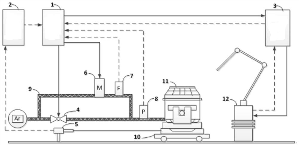
[0056] A system for automatically blowing argon in a ladle, refer to figure 2 , including argon blowing control module 1, blowing control module 2, robot control module 3, temperature measurement and sampling robot 12, valve 4, distance measurement module 5, digital flow valve 6, flow meter 7, pressure gauge 8, argon pipeline 9 , Ladle moving module 10, steel ladle 11.

[0057] Specifically, the argon blowing control module 1 is used to receive the tapping signal, the numerical value of the inclination angle of the converter and the angle of the alloy adding chute in the tapping stage, and when the inclination angle of the converter reaches a set angle, start the The argon pipeline blows and stirs the ladle strongly; when the angle of the alloy adding chute is 0 and the alloy addition is completed, the argon blowing control module closes the argon pipeline. Further, the argon blowing control module 1 is used to receive the molten steel temperature data sent by the robot cont...


PUM


Abstract

The invention relates to an automatic argon blowing method and system of steel ladles. The method comprises the following steps: S1, setting the types and target temperature Ts of steel, and detectingan automatic argon blowing interlocking condition; and S2, performing argon strong-blowing and stirring of the steel ladles when a converter inclination angle reaches a setting value in a steel discharging process, and stopping strong-blowing of the argon after alloys are processed completely; S3, detecting the temperature of molten steel in the steel ladles to obtain real-time temperature Tn; S4, calculating the argon blowing flow and the argon blowing time through a cooling model according to Tn and Ts, and performing argon blowing; and S5, measuring the temperature Ta of the molten steel in the steel ladles again, ending the argon blowing process of the steel ladles when Ta is equal to Ts, and returning to the step S4 when Ta is more than Ts. According to the automatic argon blowing method of the steel ladles provided by the invention, whole-process automatic argon blowing before feeding of the steel ladles onto a continuous casting machine at the beginning of steel output is realized, so that the labor intensity of working personnel is reduced, and the automatic argon blowing operation safety is improved.

Description

technical field [0001] The invention relates to the technical field of steelmaking, in particular to a method and system for automatically blowing argon into a ladle. Background technique [0002] The purpose of argon blowing after steelmaking mainly has four aspects: a. After stirring, the added alloy is fully melted and uniform; b. The temperature of molten steel is reduced to the temperature required for continuous casting; c. The slag inclusions float up; d. Special alloy feed Therefore, the goal of argon blowing control is also carried out around these purposes, and argon blowing is mainly achieved by adjusting and controlling the flow rate of argon blowing. In general, argon blowing can be divided into side blowing, strong blowing, and soft blowing. Strong blowing can achieve a purpose and b purpose, and make the temperature drop rapidly; ordinary blowing or soft blowing are less powerful, which can reduce the exposure of molten steel degree, and promote the floating ...

Claims


Application Information

Patent Timeline
Patent Type & Authority Applications(China)
IPC IPC(8): C21C7/072B22D11/117B22D11/16
CPCC21C7/072B22D11/117B22D11/16Y02P10/25
Inventor 李明龙
Owner WISDRI ENG & RES INC LTD
Why Eureka
Try Eureka