Three-in-one oil cooling electric driving structure

An electric drive, three-in-one technology, applied in the field of three-in-one oil-cooled electric drive structure, can solve the problems of large oil leakage risk, complicated production process and assembly process, and increased material cost, so as to reduce the risk of oil leakage, The effect of solving uneven cooling and improving cooling efficiency

Active Publication Date: 2021-02-26
HEFEI JUYI POWER SYST CO LTD
View PDF5 Cites 17 Cited by
  • Summary
  • Abstract
  • Description
  • Claims
  • Application Information

AI Technical Summary

Problems solved by technology

Among them, oil spraying requires specially designed injection molded parts for oil separation, which increases material costs and may cause the risk of abnormal sound
The oil injection structure needs to design a special copper tube with holes for spraying. The production process and assembly process are very complicated, and the small holes of the copper tube may be blocked, which will prevent the motor stator from being effectively cooled.
The existing oil-cooled electric drive structure is generally not compact enough in the design of the oil-cooled cooling circuit, and many oil pipes need to be connected externally, such as oil pumps, oil coolers and other components, which not only increase the cost but also have a great risk of oil leakage

Method used


Image

  • Three-in-one oil cooling electric driving structure
  • Three-in-one oil cooling electric driving structure
  • Three-in-one oil cooling electric driving structure

Examples


Embodiment

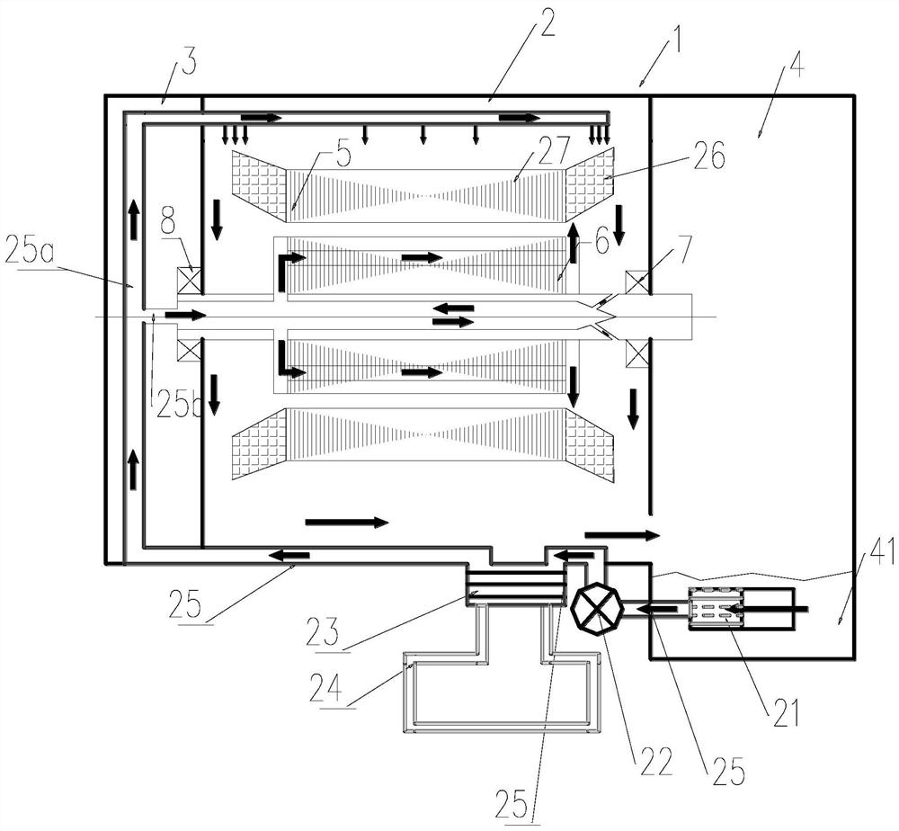
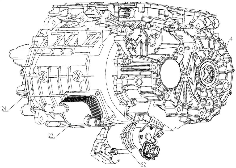
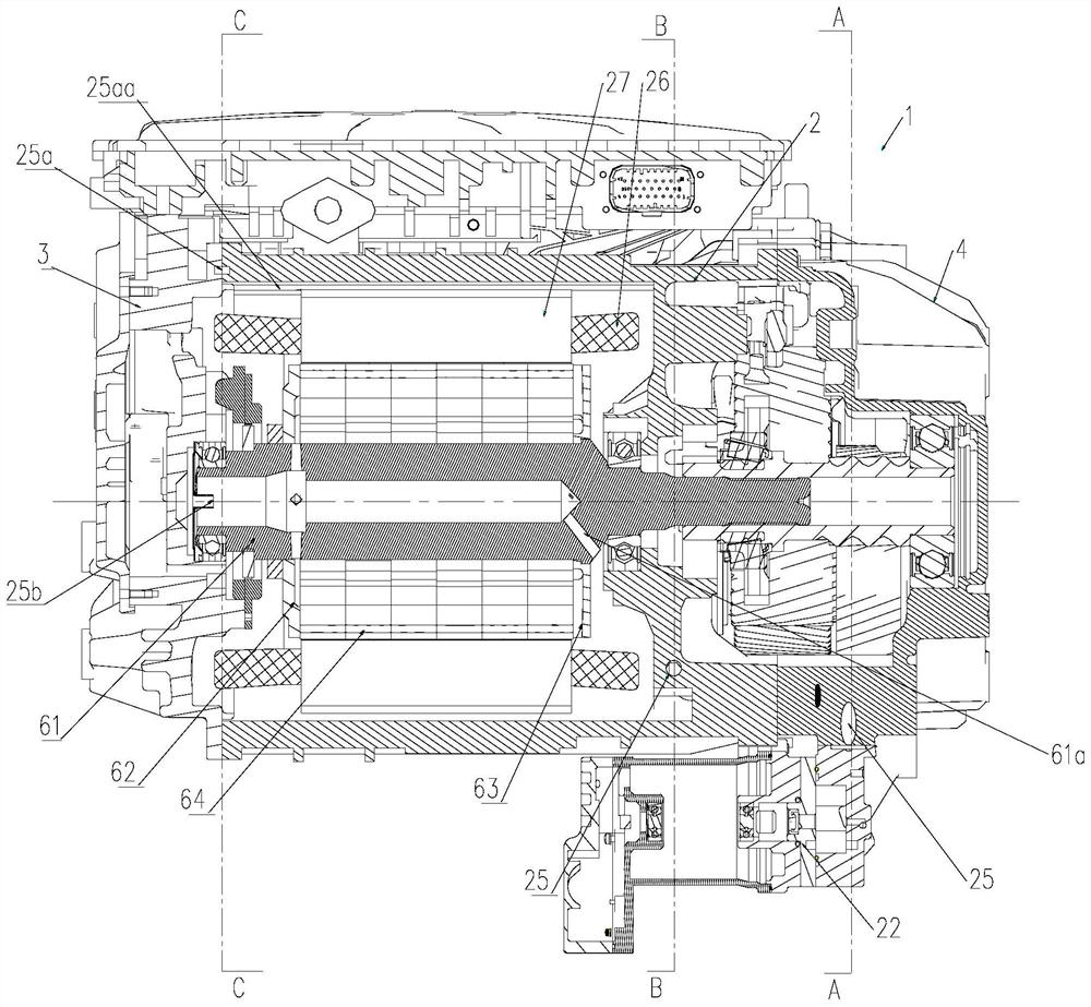
[0043] Embodiment: This application provides a three-in-one oil-cooled electric drive structure, which mainly uses the lubricating oil of the reducer itself. After filtering through the filter, the oil pump provides power, and after cooling, it enters the electric drive. Among them, the oil circuit is cooled Finally, the rear end cover is divided into two paths, one path enters the rotor to cool the rotor and bearings, and the other path enters the housing to cool the stator, and finally the oil drops to the lower part of the motor due to power, and flows back to the reducer to complete the entire cooling cycle. combined reference Figure 1 to Figure 13 , the three-in-one oil-cooled electric drive structure 1 includes: an oil-cooled structure from the reducer integrated with the electric drive housing to the rear end of the motor, a rotor cooling structure, and a stator cooling structure. The electric drive housing includes a motor housing 2, a rear end cover 3, and a reducer...


PUM


Abstract

The invention discloses a three-in-one oil cooling electric drive structure which comprises a speed reducer-to-motor rear end oil cooling structure integrated with an electric drive shell, a rotor cooling structure and a stator cooling structure. The speed reducer-to-motor rear end oil cooling structure conveys cooling oil in a speed reducer shell into a main oil way of the motor shell, the main oil way is divided into a first oil way and a second oil way on a rear end cover, the first oil way is communicated with the stator cooling structure, and the second oil way is communicated with the rotor cooling structure. The stator cooling structure is used for introducing cooling oil into the upper part of the electric drive, and directionally cooling the stator through an oil spraying hole ina stator oil distribution channel in the motor shell; the rotor cooling structure is used for rotating and throwing cooling oil through a rotor to achieve cooling. A circulating oil way is connected through the structural design of the shell, the oil way is shunted on the shell, cooling of the stator and the rotor is guaranteed, an additional oil distributing structure and an additional copper pipe are not needed, the integration degree of oil cooling electric drive is improved, the cost is reduced, and the risk of oil leakage of an oil pipe is reduced.

Description

technical field [0001] The invention belongs to the technical field of oil cooling and relates to a three-in-one oil cooling electric drive structure. Background technique [0002] With the popularity of new energy vehicles, the market's demand for the performance of electric vehicle power systems continues to increase, and the volume and power density required for electric drive systems are also getting higher and higher. That is to say, the structure of the power system needs to be as compact and light as possible. Therefore, the market is currently focusing on the "three-in-one" product structure integrating the three units of the main drive motor + reducer + controller. However, the traditional water-cooling scheme cannot directly cool the heat source, and there is thermal resistance. So there is a temperature gradient from the motor windings to the water-cooled casing. The winding cannot be cooled directly, causing temperature to build up and form localized hot spots....

Claims


Application Information

Patent Timeline
Patent Type & Authority Applications(China)
IPC IPC(8): H02K9/19H02K5/20H02K1/20H02K1/32H02K3/24H02K1/28H02K5/16H02K7/10H02K7/116
CPCH02K9/19H02K5/20H02K1/20H02K1/32H02K3/24H02K1/28H02K5/161H02K7/10H02K7/116Y02T10/64
Inventor 刘蕾程勇张平平郭殿伟
Owner HEFEI JUYI POWER SYST CO LTD
Why Eureka
Try Eureka