
Porous structure fusion cage

A technology of porous structure and fusion device, applied in the direction of spinal implants, etc., can solve the problems of reducing fatigue strength of fusion device, reducing elastic modulus, and deposition of internal implants, so as to facilitate adhesion and growth, reduce elastic modulus, etc. amount, avoiding the effect of stress avoidance

Pending Publication Date: 2021-03-02
SHANGHAI KINETIC MEDICAL
View PDF0 Cites 0 Cited by
  • Summary
  • Abstract
  • Description
  • Claims
  • Application Information

AI Technical Summary

Problems solved by technology

Anterior decompression and fusion for cervical spondylosis is the first choice for degenerative cervical spondylosis that is ineffective in conservative treatment. However, the overall elastic modulus of the titanium alloy fusion cage used in the current clinical stage is high, and it is easy to produce implantation when it is directly applied to the vertebral body. Injection deposition, "stress avoidance" and other conditions, so solid titanium alloy interbody fusion is not suitable for clinical use
At present, titanium alloy implanted with porous structure is mostly used, but the middle part of the existing porous structure cage body has a cavity, which reduces the fatigue strength of the cage while reducing the elastic modulus, resulting in failure of the cage after surgery.

Method used


Image

  • Porous structure fusion cage
  • Porous structure fusion cage
  • Porous structure fusion cage

Examples


Embodiment Construction

[0047] In order to more clearly illustrate the embodiments of the present invention or the technical solutions in the prior art, the specific implementation manners of the present invention will be described below with reference to the accompanying drawings. Obviously, the accompanying drawings in the following description are only some embodiments of the present invention, and those skilled in the art can obtain other accompanying drawings based on these drawings and obtain other implementations.

[0048]In order to make the drawing concise, each drawing only schematically shows the parts related to the present invention, and they do not represent the actual structure of the product. In addition, to make the drawings concise and easy to understand, in some drawings, only one of the components having the same structure or function is schematically shown, or only one of them is marked. Herein, "a" not only means "only one", but also means "more than one".

[0049] According t...


PUM


Abstract

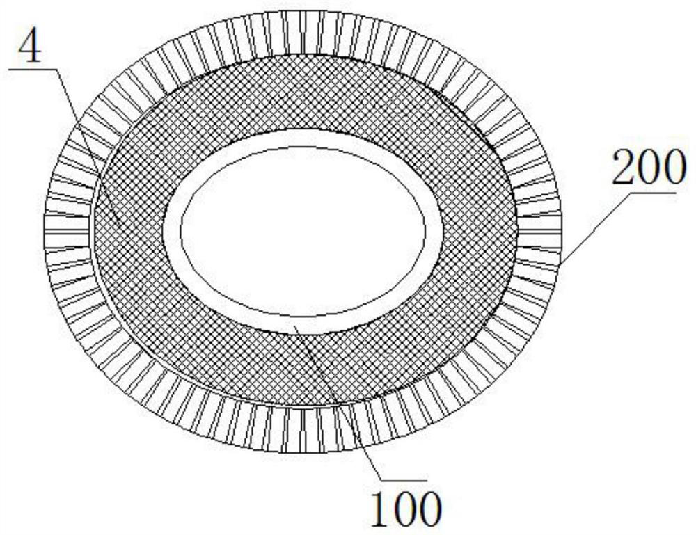
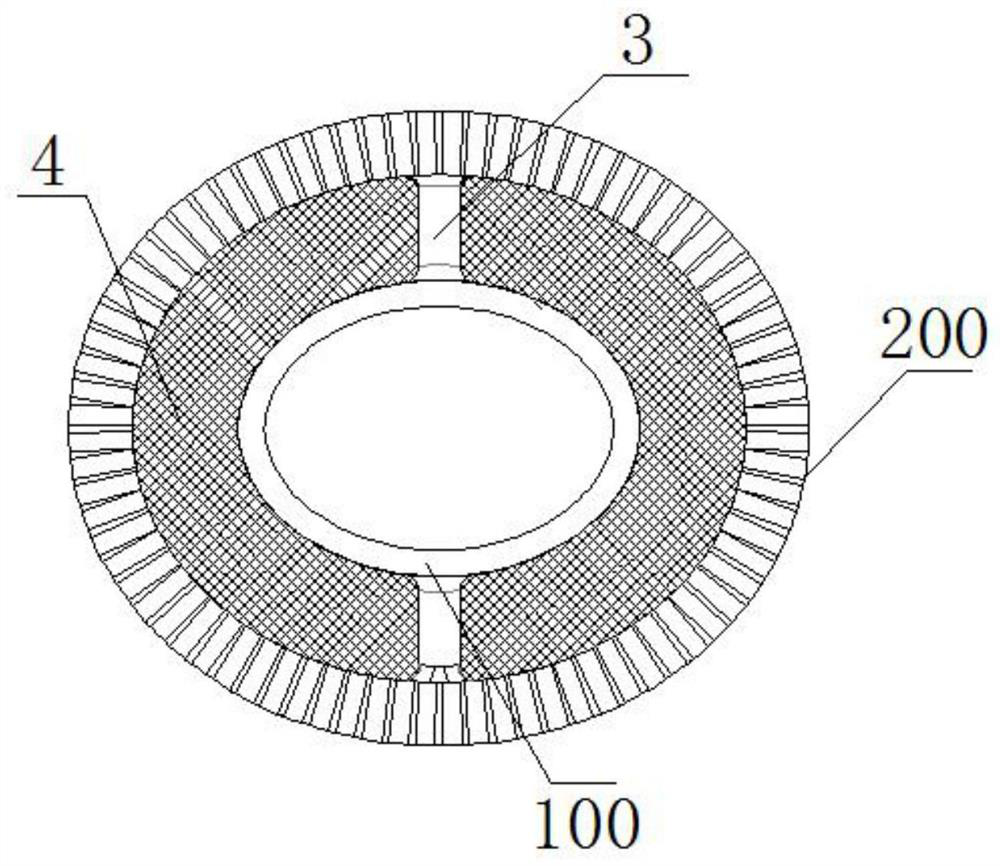
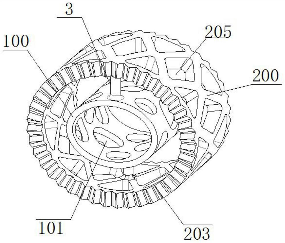
The invention provides a porous structure fusion cage which comprises a cylindrical part, a fusion cage body arranged on the cylindrical part in a sleeving mode and a loosening and distraction part; the loosening and distraction part is arranged between the cylindrical part and the fusion cage body and used for connecting the fusion cage body and the cylindrical part. the loosening and distractionpart is of a porous structure formed by connecting a plurality of unit cell structure arrays, and each unit cell structure is of a bipyramid structure formed by connecting a plurality of micro-rods.By modifying the interior of an existing fusion cage body, proliferation, differentiation and growth of osteoblasts are facilitated, and a tight intraosseous implantation interface is formed; and dueto the filling of the unit cell structures, the implanted fusion cage body can form tight callus and bone bridges more easily, and bone ingrowth is more facilitated.

Description

technical field [0001] The invention relates to the field of medical instruments, in particular to a fusion device with a porous structure. Background technique [0002] Intervertebral joint degeneration and surrounding tissue compression caused by chronic strain are the main causes of cervical spondylosis. A series of cervical nerve root syndromes often seriously affect the lives of patients. Anterior decompression and fusion for cervical spondylosis is the first choice for degenerative cervical spondylosis that is ineffective in conservative treatment. However, the overall elastic modulus of the titanium alloy fusion cage used in the current clinical stage is high, and it is easy to produce implantation when it is directly applied to the vertebral body. Therefore, solid titanium alloy intervertebral fusion cages are not suitable for clinical application. At present, titanium alloy implanted with porous structure is mostly used, but the middle part of the existing porous s...

Claims


Application Information

Patent Timeline
Patent Type & Authority Applications(China)
IPC IPC(8): A61F2/44
CPCA61F2/4455
Inventor 蔡方舟丁伟
Owner SHANGHAI KINETIC MEDICAL
Learn More