
Vacuum impregnation method

A vacuum impregnation and vacuum technology, applied in drying/dipping machine and other directions, can solve the problems of high cost, complex process, huge equipment, etc., and achieve the effect of low equipment cost, simple process and improved product performance

Inactive Publication Date: 2021-03-02
WUXI XIYUAN BOILER
View PDF2 Cites 1 Cited by
  • Summary
  • Abstract
  • Description
  • Claims
  • Application Information

AI Technical Summary

Problems solved by technology

[0003] At present, the commonly used vacuum impregnation treatment of capacitors is to put the capacitors in a vacuum tank, and use double pumping single injection, group pumping single injection and other treatment methods. The process is complicated, and the equipment used is huge and costly.

Method used


Image

  • Vacuum impregnation method
  • Vacuum impregnation method
  • Vacuum impregnation method

Examples


Embodiment 1

[0042] The vacuum impregnation method of the present embodiment, flow process is as image 3 As shown, the steps are as follows:

[0043] 1. Preheating, heating the capacitor, the heating temperature is 130~150°C, it can be preliminarily dried, and the limit on the electrolytic paper can also be removed;

[0044] 2. Canning, put the heated capacitor into the dipping tank 2 in the tank body 1;

[0045] 3. Vacuumize, start the vacuum unit 4, and keep the vacuum degree in the tank body 1 below 9Pa;

[0046] 4. Inflate, fill the tank body 1 with argon;

[0047] 5. Heating, heating the inside of the tank body 1, the heating temperature is 130~150°C;

[0048] 6. Secondary vacuuming, start the vacuum unit 4, and control the vacuum degree in the tank 1 below 8Pa;

[0049] 7. Liquid injection impregnation, inject electrolyte solution into the capacitor, make it impregnate for 10~13 hours, keep constant pressure and temperature during impregnation;

[0050] 8. Take it out, stop hea...

Embodiment 2

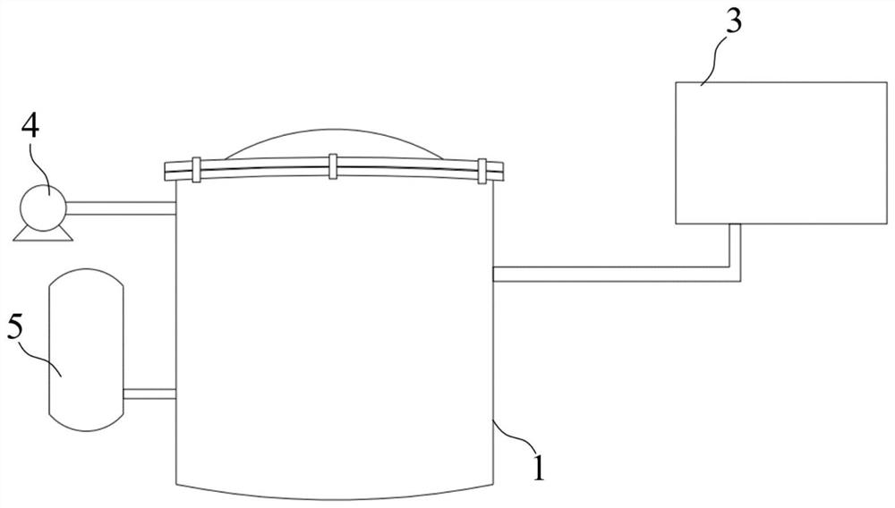
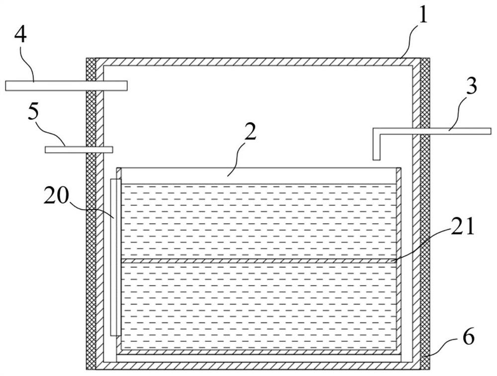
[0052] The vacuum impregnation method of this embodiment is further improved on the basis of Example 1, and vacuum impregnation is carried out based on the following vacuum impregnation tanks, including:

[0053] Tank 1;

[0054] An immersion tank 2, which is arranged inside the tank body 1, is used to accommodate capacitors and electrolyte;

[0055] Liquid injection unit 3, which is located outside the tank body 1 and communicates with the inside of the tank body 1, stores electrolyte and injects liquid into the dipping tank 2;

[0056] The vacuum unit 4 is located outside the tank body 1 and communicates with the inside of the tank body 1 to provide a negative pressure environment inside the tank body 1;

[0057] Inflatable unit 5, which is located outside the tank body 1, communicates with the inside of the tank body 1, and inflates the inside of the tank body 1;

[0058] The heating unit 6 provides heat to the inside of the tank body 1 .

[0059] The vacuum impregnation...

Embodiment 3

[0062] The vacuum impregnation method of this embodiment is further improved on the basis of embodiment 2. The dipping tank 2 is provided with a liquid level gauge 20 to detect the height of the electrolyte in the dipping tank 2 .

[0063] like figure 2 As shown, in this embodiment, the liquid level gauge 20 is set in the immersion tank 2, and the liquid level gauge 20 is connected with the signal of the liquid injection unit 3, so that the height of the electrolyte in the immersion tank 2 can be monitored in real time, so as to avoid electrolyte overflow or electrolyte leakage. Insufficiency occurs.


PUM


Abstract

The invention discloses a vacuum impregnation method, and belongs to the technical field of vacuum impregnation. The vacuum impregnation method comprises the following steps of: 1, preheating, namelyheating a capacitor; 2, canning, namely putting the heated capacitor into a dipping tank in a tank body; 3, vacuumizing, , namely starting a vacuum unit to keep a negative pressure state in the tank body; 4, gas charging, namely charging argon into the tank body; 5, heating, namely heating the interior of the tank body; 6, secondary vacuumizing, namely starting a vacuum unit, and controlling the vacuum degree in the tank body to be below 8Pa; 7, liquid injection and impregnation, which is implemented by injecting an electrolyte into the capacitor to impregnate the capacitor for 1013 hours, andkeeping constant pressure and constant temperature during impregnation; and 8, taking out, namely stopping heating the tank body, and taking out the capacitor after the tank body returns to a normal-temperature and normal-pressure state. The vacuum impregnation method is simple in process, good in impregnation effect and high in impregnation efficiency, and the product performance is improved.

Description

technical field [0001] The invention belongs to the technical field of vacuum impregnation, and more specifically relates to a vacuum impregnation method. Background technique [0002] In the production process of capacitors, vacuum impregnation is an important and necessary process. Through the vacuum impregnation process, the capacitor is placed in a vacuum environment to remove the air and volatiles inside the coil, relying on the gravity of the paint liquid in the vacuum environment and the capillary action of the coil , and use dry compressed air or inert gas to apply a certain pressure to the impregnating varnish after the vacuum is released, so that the varnish quickly penetrates and fills the interior of the insulating structure. This process is of great help to improve the electrical performance of the capacitor. [0003] At present, the commonly used vacuum impregnation treatment of capacitors is to put capacitors into vacuum tanks, and adopt double pumping single ...

Claims


Application Information

Patent Timeline
Patent Type & Authority Applications(China)
IPC IPC(8): H01G13/04
CPCH01G13/04
Inventor 冯晓宏
Owner WUXI XIYUAN BOILER
Learn More