
Antenna Module and Terminal

An antenna module and terminal technology, which is applied to antennas, loop antennas, antenna arrays, etc., can solve the problem of large space occupied by antenna modules, and achieve the effect of reducing space occupation, reducing quantity and increasing quantity.

Active Publication Date: 2022-03-01
BEIJING XIAOMI MOBILE SOFTWARE CO LTD
View PDF19 Cites 0 Cited by
  • Summary
  • Abstract
  • Description
  • Claims
  • Application Information

AI Technical Summary

Problems solved by technology

[0004] The present disclosure provides an antenna module and a terminal, which can solve the problem that the antenna module occupies too much space in the related art

Method used


Image

  • Antenna Module and Terminal
  • Antenna Module and Terminal
  • Antenna Module and Terminal

Examples


Embodiment Construction

[0051] In order to make the purpose, technical solution and advantages of the present disclosure clearer, the implementation manners of the present disclosure will be further described in detail below in conjunction with the accompanying drawings.

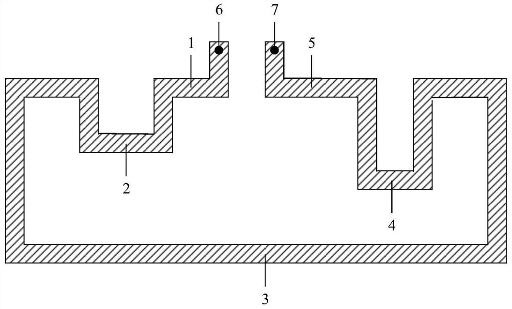
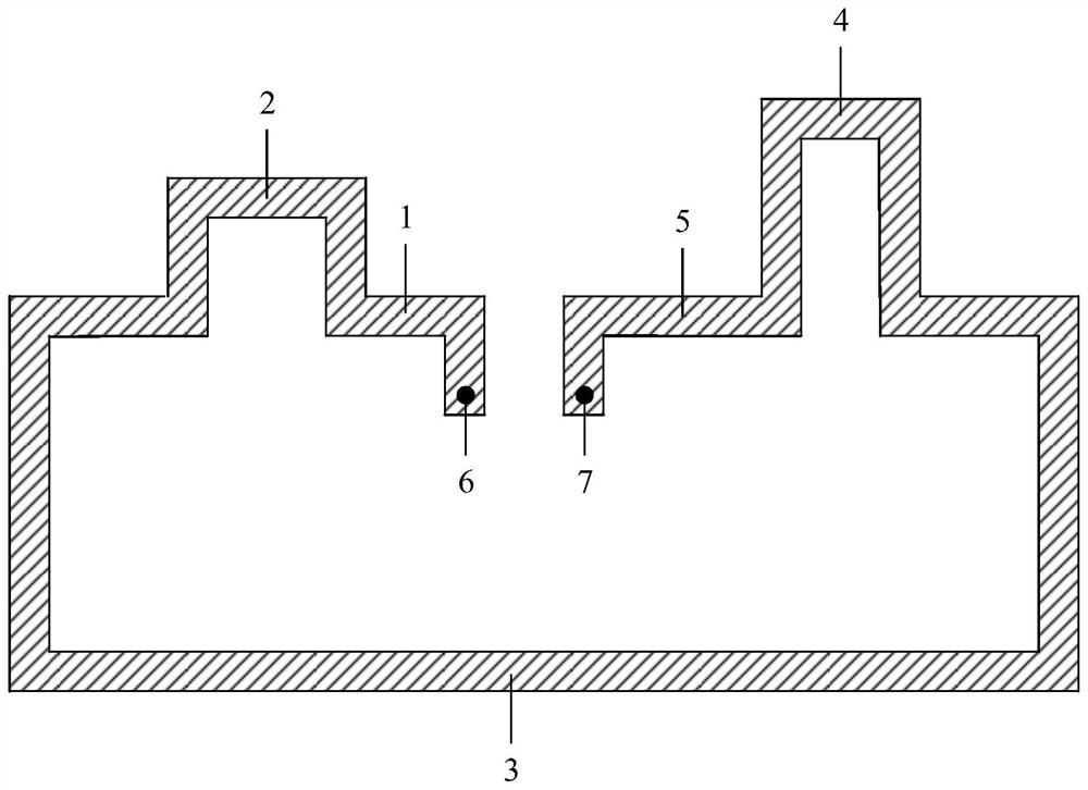
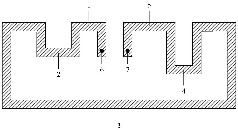
[0052] Figure 1 to Figure 6 is a schematic structural diagram of an antenna module shown according to an exemplary embodiment, see Figure 1 to Figure 6 , the antenna module includes a feeding stub 1 , a first stub 2 , a second stub 3 , a third stub 4 and a grounding stub 5 .

[0053] The feeding branch 1 is connected to the feeding point 6, the grounding branch 5 is connected to the grounding point 7, the first branch 2 and the third branch 4 are concave branches, and the second branch 3 is a bent branch.

[0054] Wherein, by adjusting the distance between the feed point 6 and the ground point 7, the input impedance of the antenna module can be adjusted.

[0055]Moreover, the ratio between the output impedance and the input imp...


PUM


Abstract

The disclosure provides an antenna module and a terminal, which belong to the technical field of communications. The device includes: a feeding branch, a first branch, a second branch, a third branch and a grounding branch; the feeding branch is connected to a feeding point, and the grounding branch is connected to a grounding point; the first branch The node and the third branch are concave branches; the second branch is a bent branch; the feeder branch, the first branch, the second branch, the third branch and The grounding branches are connected in sequence to form an annular structure with a slot, the slot is located between the feeding branch and the grounding branch, and the inside of the slot is insulated. The embodiment of the present disclosure provides an antenna module combining a ring structure and an inverted F structure. The antenna module can work in multiple frequency bands, which improves the performance of the antenna module and can meet the requirements of MIMO antennas without setting up multiple antenna modules. Radiation performance requirements, saving space for the layout of other electronic devices of the terminal.

Description

technical field [0001] The present disclosure relates to the field of communication technologies, and in particular to an antenna module and a terminal. Background technique [0002] With the continuous development of communication technology, it has gradually entered the multi-network era, 4G (The 4th Generation Mobile Communication Technology, the fourth generation mobile communication technology), WIFI (Wireless-Fidelity, wireless network), 5G (The 5th Generation Mobile Communication Technology , fifth-generation mobile communication technology) and other communication networks are gradually emerging. Since the frequency bands of different communication networks are different, in order to be compatible with different communication networks and meet the radiation performance requirements of MIMO (Multiple-Input Multiple-Output, multiple-input multiple-output system) antennas, the terminal needs to support frequency bands of multiple communication networks. [0003] The an...

Claims


Application Information

Patent Timeline
Patent Type & Authority Patents(China)
IPC IPC(8): H01Q1/36H01Q1/48H01Q1/50
CPCH01Q1/36H01Q1/48H01Q1/50H01Q7/00H01Q5/364H01Q1/46H01Q21/064H01Q1/243H01Q1/00H01Q5/00H01Q9/0464H04M1/026
Inventor 王亚丽
Owner BEIJING XIAOMI MOBILE SOFTWARE CO LTD
Learn More