
Millimeter-wave ultra-wideband log-periodic antenna based on multilayer PCB

A logarithmic periodic antenna and millimeter wave technology, applied to antennas, antenna arrays, resonant antennas, etc., can solve problems such as reporting and lack of ideas, and achieve the effect of wide bandwidth, small physical size, and increased gain

Active Publication Date: 2021-03-05
ANHUI UNIVERSITY
View PDF12 Cites 1 Cited by
  • Summary
  • Abstract
  • Description
  • Claims
  • Application Information

AI Technical Summary

Problems solved by technology

There have been a lot of work reports on the design of logarithmic periodic antennas, but there is no report on the idea of ​​this design

Method used


Image

  • Millimeter-wave ultra-wideband log-periodic antenna based on multilayer PCB
  • Millimeter-wave ultra-wideband log-periodic antenna based on multilayer PCB
  • Millimeter-wave ultra-wideband log-periodic antenna based on multilayer PCB

Examples


Embodiment

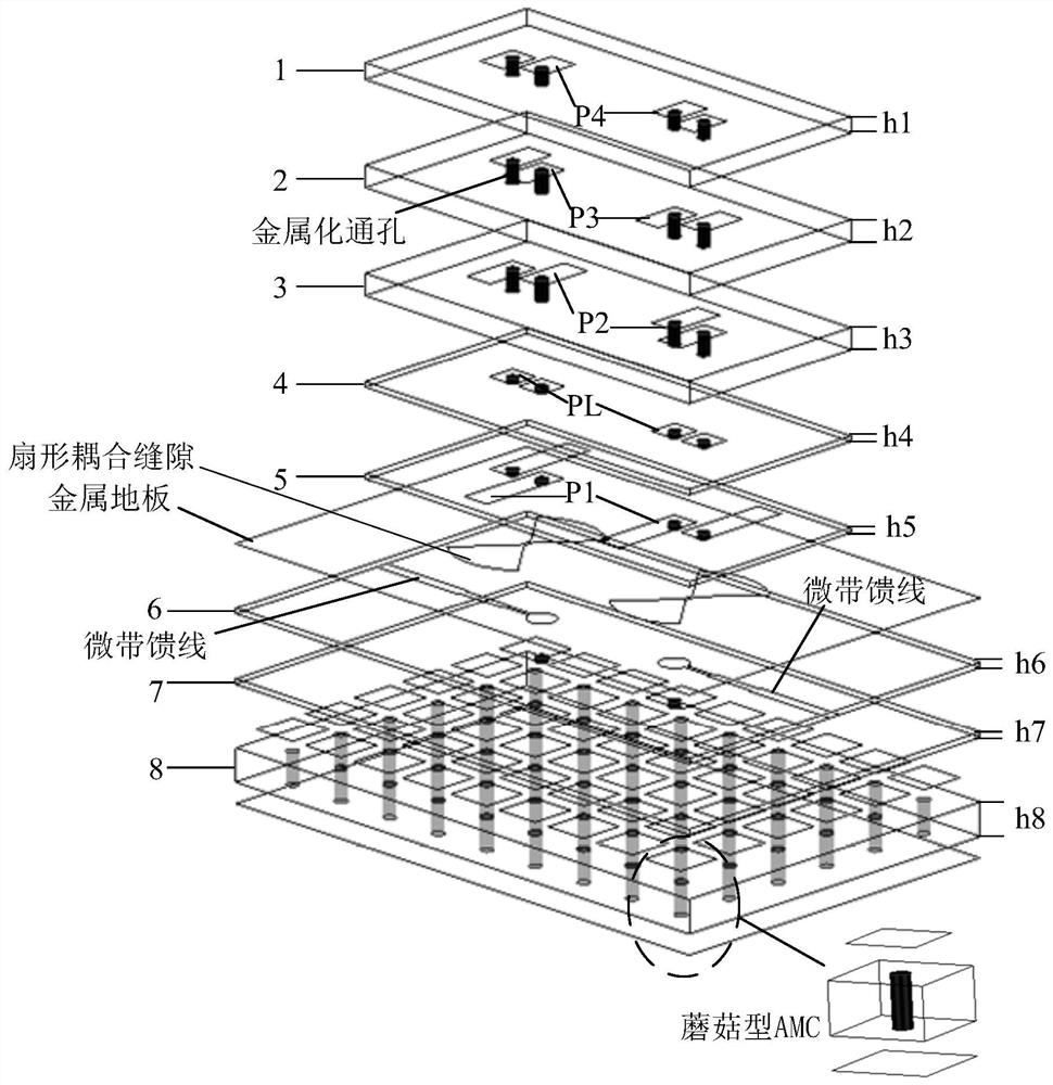
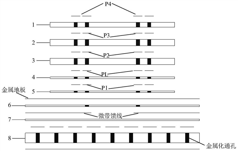
[0040] For the working antenna of the ultra-wideband wireless communication system, this embodiment designs an easily integrated millimeter-wave ultra-wideband array antenna based on a multilayer PCB, which can be used in a wireless communication system. The antenna can cover the frequency band of 32.5-46.5GHz, and can also be optimized to cover a wider frequency band. The antenna mainly includes structures such as a radiator, a dielectric base metal ground plane, and a microstrip balun feed.

[0041] The antenna radiator is composed of multi-layer PCB and connected with different radiation branches by short-circuit pins. The maximum length of the radiation stub is approximately half the wavelength of the lowest frequency point; the minimum length is approximately the half wavelength of the highest frequency point.

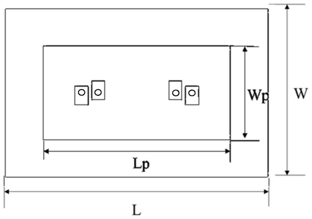
[0042] The millimeter-wave ultra-wideband logarithmic periodic array antenna involved in the above-mentioned embodiment, its schematic diagram is as follows fig...


PUM

PropertyMeasurementUnit
thicknessaaaaaaaaaa
dielectric lossaaaaaaaaaa

Abstract

The invention provides a millimeter-wave ultra-wideband log-periodic antenna based on a multilayer PCB. The millimeter-wave ultra-wideband log-periodic antenna comprises multilayer PCB dielectric substrates, an antenna radiator, a metallized through hole and a microstrip feeder line, and the metallized through hole is formed in the PCB dielectric substrate; the multiple layers of PCB dielectric substrates are stacked, and each PCB dielectric substrate comprises a feed layer dielectric substrate, a plurality of first substrates arranged above the feed layer dielectric substrate and a second substrate arranged below the feed layer dielectric substrate; radiation branches are arranged on the upper surfaces of the multiple first substrates, and the metallized through holes of every two adjacent first substrates are connected through the radiation branches; a fan-shaped gap is etched in the copper-clad layer above the feed layer dielectric substrate and is coupled with a microstrip feeder line arranged below the feed layer dielectric substrate for feeding; and the second substrate at the bottommost layer forms an AMC structure. According to the invention, a multi-layer PCB structure isused, so that the antenna has the advantages of low profile, easy integration and the like during array formation.

Description

technical field [0001] The present invention relates to the technical field of antennas, in particular to a multilayer PCB-based millimeter-wave ultra-wideband logarithmic periodic antenna. Background technique [0002] The current wireless communication technology is developing rapidly to meet people's demand for information. With the advent of the 5G era, millimeter-wave frequency bands are gradually being used more and more, and the design of millimeter-wave antennas becomes very necessary. The millimeter-wave ultra-wideband antenna can reduce the use of a large number of antennas, thereby reducing the size of the wireless communication system. There are also a lot of work in the direction of millimeter-wave ultra-wideband antennas at home and abroad. The invention improves the logarithmic period antenna and applies it to millimeter wave ultra-wideband. There have been a lot of work reports on the design of logarithmic periodic antennas, but there is no report on the i...

Claims


Application Information

Patent Timeline
Patent Type & Authority Applications(China)
IPC IPC(8): H01Q1/38H01Q21/00H01Q9/04
CPCH01Q1/38H01Q21/00H01Q9/04
Inventor 徐光辉黄道胜杨利霞黄志祥
Owner ANHUI UNIVERSITY
Learn More