Coiling control method and device

A control method and coiler technology, applied in rolling mill control devices, metal rolling, manufacturing tools, etc., can solve problems such as stacking accidents, failure to switch coilers at the end position, and reduced production efficiency

Active Publication Date: 2021-03-09
SHOUGANG JINGTANG IRON & STEEL CO LTD
View PDF5 Cites 2 Cited by
  • Summary
  • Abstract
  • Description
  • Claims
  • Application Information

AI Technical Summary

Problems solved by technology

[0005]Aiming at the problems existing in the prior art, the embodiment of the present invention provides a coiling method and device, which are used to solve the problem of using multiple coilers in the prior art. When the machine is coiling the strip steel, the last coiler cannot be smoothly switched to the first coiler, resulting in a pile of steel accidents, which in turn leads to a technical problem of reduced production efficiency

Method used


Image

  • Coiling control method and device
  • Coiling control method and device

Examples


Embodiment 1

[0041] This embodiment provides a coiling control method, which is applied in a hot rolling production line. In order to understand the technical solution of the present invention more clearly, the hot rolling production line is firstly introduced here. Taking the running direction of the strip as a reference, the hot rolling production line includes: finishing stand, layer cooling roller table, valve, pinch roller, first coiler, second coiler and third coiler; A heat detector is installed before the coiler, and each coiler has a corresponding valve and pinch roller; the valve and pinch roller can guide the strip steel so that the strip steel enters the corresponding coiler for coiling; The layer cold roller table includes nine groups.

[0042] Here, the first coiler can be understood as the first coiler, and the third coiler can be understood as the last coiler, and each coiler coils the strip in turn.

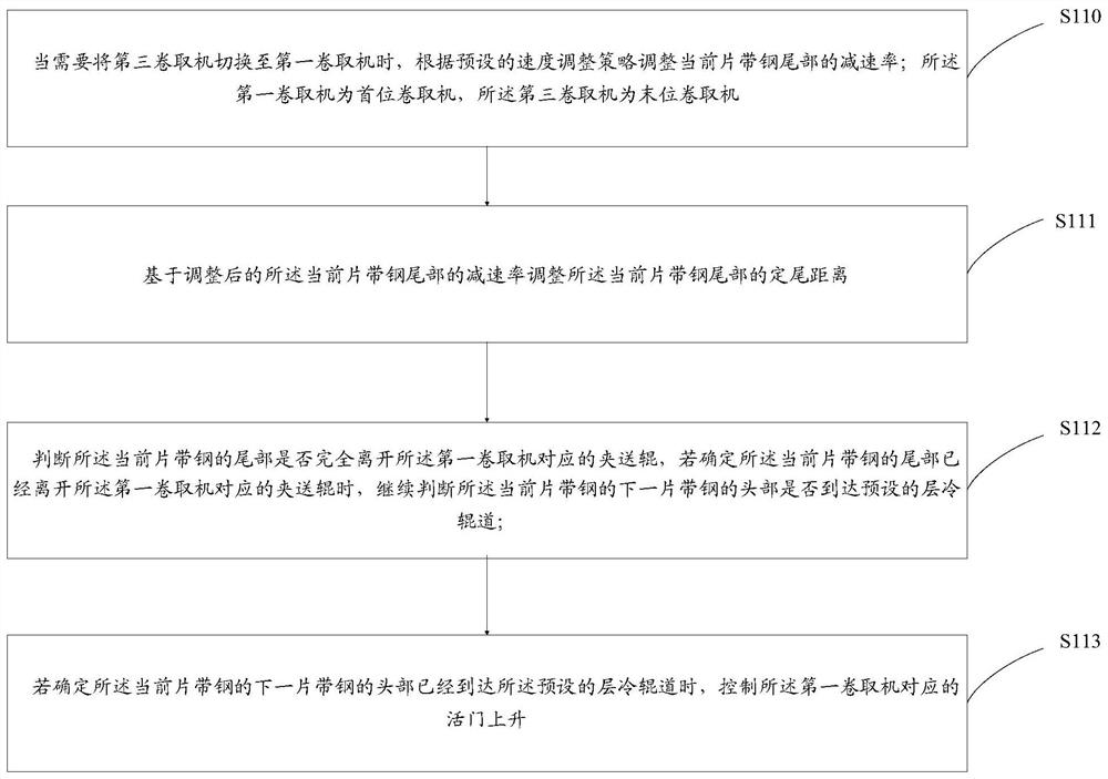
[0043] Specifically, such as figure 1 As shown, the methods include: ...

Embodiment 2

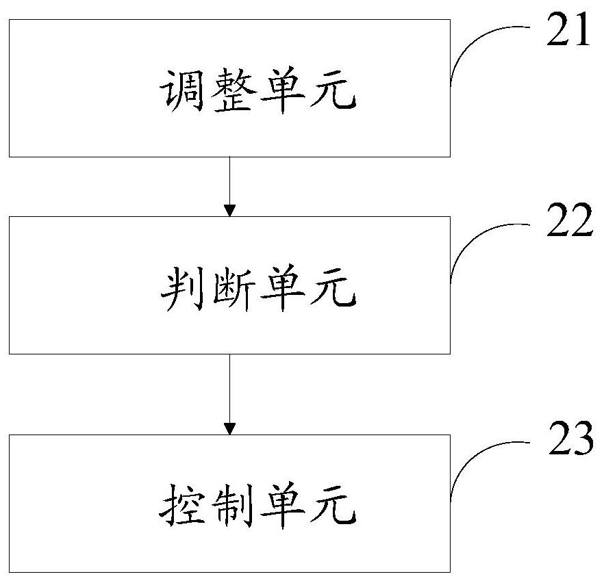
[0072] This embodiment provides a coiling control device, such as figure 2 As shown, the device includes: an adjustment unit 21, a judgment unit 22 and a control unit 23; wherein,

[0073] The adjustment unit 21 is used to adjust the deceleration rate of the tail of the current strip according to the preset speed adjustment strategy when the third coiler needs to be switched to the first coiler; the first coiler is the first coiler A take-up machine, the third coiler is a final coiler; adjust the fixed tail distance of the current strip tail based on the adjusted deceleration rate of the tail of the current strip;

[0074] Judging unit 22, configured to judge whether the tail of the current strip has completely left the pinch roller corresponding to the first coiler, if it is determined that the tail of the current strip has left the first coiler When corresponding to the pinch roller, continue to judge whether the head of the next strip of the current strip reaches the pres...

Embodiment 3

[0103] In actual application, when using the coiling control method provided in Embodiment 1 and the coiling control device provided in Embodiment 2 to coil the strip steel on a hot rolling production line, the specific implementation is as follows:

[0104] When it is necessary to switch the third coiler to the first coiler, adjust the deceleration rate of the tail of the current strip steel according to the preset speed adjustment strategy; adjust the deceleration rate based on the adjusted deceleration rate of the tail of the current strip steel Describe the fixed tail distance of the front strip steel tail; When making the front strip steel tail arrive before the heat detector installed before the third coiler, the current running speed of the front strip steel tail is consistent with the fixed tail speed.

[0105] Increase the valve rising sequence corresponding to the first coiler, and judge whether the tail of the current strip has completely left the pinch roller corres...


PUM


Abstract

The invention provides a coiling control method and device. The method comprises the steps that the deceleration rate of the tail part of a current piece of strip steel is adjusted according to a preset speed adjustment strategy when a third coiling machine needs to be switched to a first coiling machine; the tail fixing distance of the tail part of the current piece of strip steel is adjusted based on the adjusted deceleration rate of the tail part of the current piece of strip steel; whether the tail part of the current piece of strip steel completely leaves a pinch roll corresponding to thefirst coiling machine or not is judged, and if the tail part of the current piece of strip steel leaves the pinch roll, whether the head part of a next piece of strip steel of the current piece of strip steel reaches a preset layer cooling roller way or not is judged; and if the tail part of the current piece of strip steel reaches the pinch roll, a valve corresponding to the first coiling machine is controlled to ascend; According to the coiling control method and device, by adjusting the deceleration rate and the tail fixing distance of the tail part of the current piece of strip steel, thetail part of the current piece of strip steel can complete the coiling process at the fastest speed; and meanwhile, in order to increase the switching speed of the coiling machines, the switching preparation time of the first coiling machine is prolonged, so that the next piece of strip steel of the current piece of strip steel can smoothly enter the first coiling machine, the steel heaping accident is avoided, and the production efficiency is ensured.

Description

technical field [0001] The invention belongs to the technical field of hot rolling, and in particular relates to a coiling control method and device. Background technique [0002] At present, in the hot rolling production line, in order to increase the output and reduce the production cost, it is generally achieved by increasing the rolling rhythm. [0003] Generally, when coiling the steel strip, in order to increase the coiling speed, usually multiple coilers are required to coil the steel strip in turn. The rolling rhythm in the hot rolling coiling area is mainly reflected in the switching speed of the coiler, especially when the last coiler is switched to the first coiler, the speed is slow, which affects the production rhythm. [0004] After the tail of the current strip coiled by the last coiler is finished, the loading signal of the last coiler drops, and at this time the first coiler starts to prepare for the next strip. The current control method cannot guarantee ...

Claims


Application Information

Patent Timeline
Patent Type & Authority Applications(China)
IPC IPC(8): B21B37/00B21B15/00
CPCB21B37/00B21B15/00B21B2015/0057
Inventor 王超邱艳红王健李万京吕进伟刘京涛李建彬武文飞付世晓
Owner SHOUGANG JINGTANG IRON & STEEL CO LTD
Why Eureka
Try Eureka