Driverless automobile accelerator control device

A driverless car, throttle control technology, applied in the layout of the power unit control mechanism, vehicle components, transportation and packaging, etc., can solve problems such as interference with the central control system, faults, large worm gear compounding, etc., to ensure the operation effect Effect

Inactive Publication Date: 2021-03-09
NANJING COLLEGE OF INFORMATION TECH
View PDF3 Cites 0 Cited by
  • Summary
  • Abstract
  • Description
  • Claims
  • Application Information

AI Technical Summary

Problems solved by technology

[0004] Aiming at the deficiencies in the prior art, the purpose of the present invention is to provide a throttle control device for unmanned vehicles, to solve the effect of using axial pressure shifting operation for the throttle of unmanned vehicles, but the pedals for auxiliary insertion also serve as an emergency response. The artificial manual operation effect wil

Method used


Image

  • Driverless automobile accelerator control device
  • Driverless automobile accelerator control device
  • Driverless automobile accelerator control device

Examples


Embodiment 1

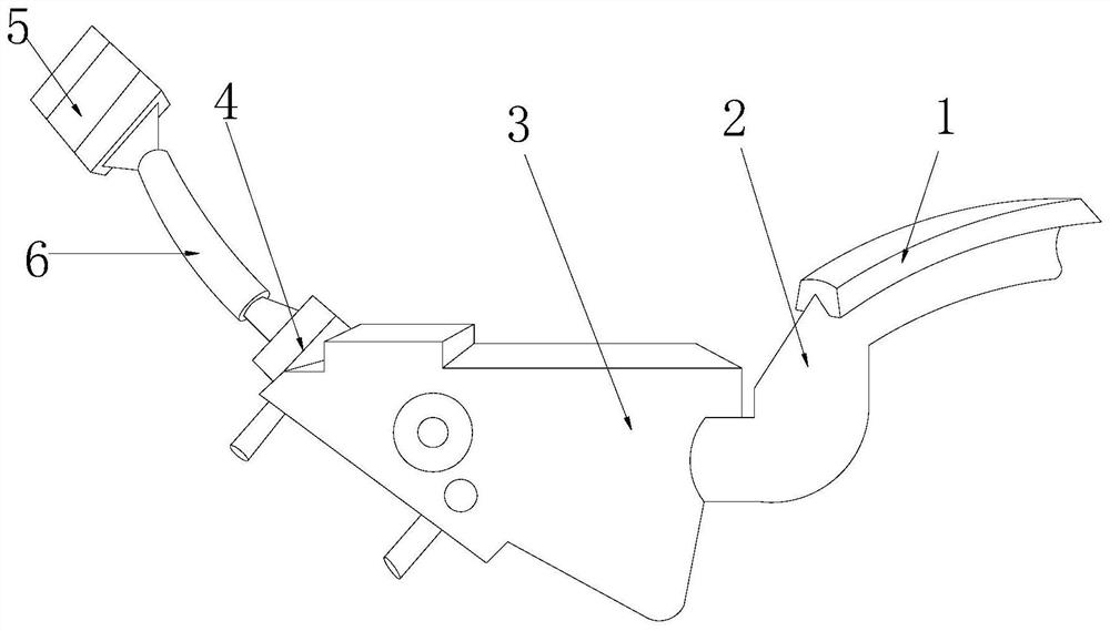
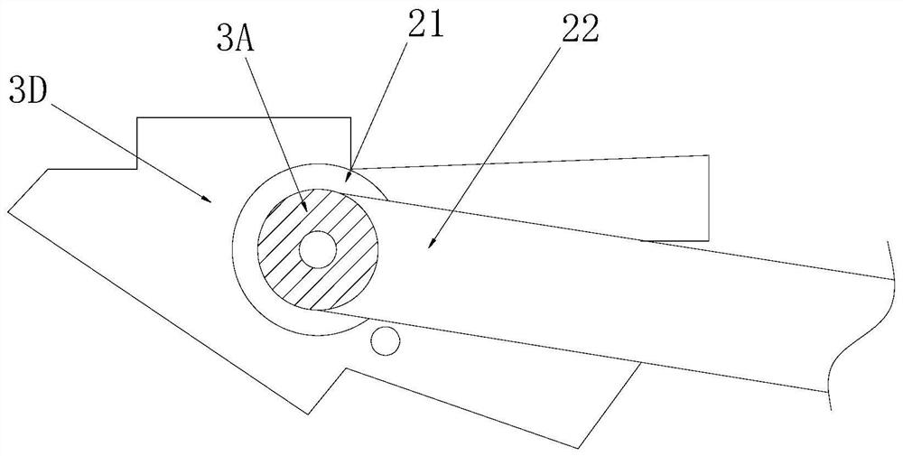
[0031] Such as Figure 1-Figure 8 As shown, the present invention provides an accelerator control device for unmanned vehicles, its structure includes: accelerator pedal 1, linkage pressure bar 2, gear position relay wheel seat 3, contact electric board seat 4, parallel plug slot 5, The wire harness sleeve 6, the gear relay wheel seat 3 is mechanically connected with the linkage pressure rod 2 and is on the same vertical plane, the accelerator pedal 1 is nested at one end of the linkage pressure rod 2 and is perpendicular to each other, the The gear relay wheel seat 3 is electrically connected with the contact electric board seat 4 and is on the same vertical plane. The contact electric board seat 4 is electrically connected with the parallel plug slot 5 through the wire harness casing 6. The gear The position relay wheel base 3 is provided with a fifth-gear wheel brush groove 3A, a damping pad frame 3B, an ellipsoid gasket 3C, and an accelerator seat shell groove 3D, and the ...

Embodiment 2

[0039] Such as Figure 1-Figure 8 As shown, the present invention provides a kind of accelerator control device for unmanned vehicles, and other aspects are the same as embodiment 1, and the difference is:

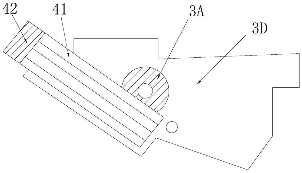
[0040] Such as image 3 As shown, the contact electric board seat 4 includes: a contact electric board 41 and a branching sleeve cap 42, the contact electric board 41 is installed under the bottom of the branching sleeve cap 42 and is on the same slope, the The contact plate 41 is nested together with the branching cap 42, and the four-position tap operation effect is formed at the bottom of the branching cap 42 through the contact plate 41, ensuring that the four gears after the reserved space are gradually increased in speed The effect of electric signal docking operation.

[0041] Such as Figure 6 As shown, the contact electric board 41 includes: a three-phase contact plate seat 411 and an integrated strip 412, the three-phase contact plate seat 411 is installed ins...


PUM


Abstract

The invention discloses a driverless automobile accelerator control device which structurally comprises an accelerator pedal, a linkage pressing rod, a gear relay wheel seat, a contact electric plateseat, a doubling plug groove and a wire harness sleeve. According to the invention, the linkage pressing rod is matched with the gear relay wheel seat; By arranging a contact electric plate base at the position of a five-gear wheel brush groove support for pressing and attaching electric signal transmission, it is guaranteed that a ratchet wheel ring frame is in butt joint with a pressing rod bodyto ascend and descend in time, when an accelerator is automatically regulated and controlled, the ratchet wheel ring frame in butt joint with the pressing rod body presses the five-gear wheel brush groove in a wrapping mode for linkage operation, and rotation continues to be in butt joint with electric signals; and a loop feedback electric signal instruction can be timely converted into a manualoperation pedal input electric signal instruction for feedback adjustment when the automobile is not driven, so that the guarantee operation effect of the automobile safety performance component framework is achieved.

Description

technical field [0001] The invention relates to an accelerator control device for an unmanned vehicle, which belongs to the field of automobiles. Background technique [0002] The self-regulating operation of vehicle components such as steering wheel self-control and throttle self-control of driverless cars is the intelligent feature of improving driverless technology, and it is also the effect of maintaining value artificial intelligence instead of human labor operation and reducing the driver's complex and efficient adaptive driving operation effect. The current technology Common disadvantages to be optimized are: [0003] The accelerator of the unmanned car adopts the effect of axial pressure shifting operation, but the auxiliary plugged pedal also has the effect of emergency manual operation, which will cause interference with the central control during the emergency automatic driving operation when the manual operation is docked. system, and the disordered output of el...

Claims


Application Information

Patent Timeline
IPC IPC(8): B60K26/02
CPCB60K26/02
Inventor 段付德
Owner NANJING COLLEGE OF INFORMATION TECH
Why Eureka
Try Eureka