
Adhesive chuck member, pattern forming method thereof, substrate clamping method and system

A chuck plate and substrate technology, applied in the direction of internal accessories, electrical components, electric solid devices, etc., can solve the problems of reduced stability, damage to the substrate, inability to separate the substrate and the chuck plate, etc., and achieve minimization due to deformation, The effect of flexible lifting

Active Publication Date: 2021-03-09
YAS
View PDF8 Cites 1 Cited by
  • Summary
  • Abstract
  • Description
  • Claims
  • Application Information

AI Technical Summary

Problems solved by technology

[0010] As an additional problem, the following problem can be cited: After the substrate and the adhesive have been stably separated after the deposition process, the substrate and the chuck plate are still not separated due to static electricity generated between the substrate and the chuck plate, and the substrate is damaged. question
[0012] In addition, it is also pointed out that due to the influence of increased sagging of the weight of the substrate due to the recent increase in the area of ​​the panel substrate, the adhesive is only limitedly provided on the portion of the panel substrate other than the light-emitting area to fix and support the substrate. , which acts as a destabilizing factor

Method used


Image

  • Adhesive chuck member, pattern forming method thereof, substrate clamping method and system
  • Adhesive chuck member, pattern forming method thereof, substrate clamping method and system
  • Adhesive chuck member, pattern forming method thereof, substrate clamping method and system

Examples


Embodiment Construction

[0121] Hereinafter, preferred embodiments of the present invention will be described in detail with reference to the drawings.

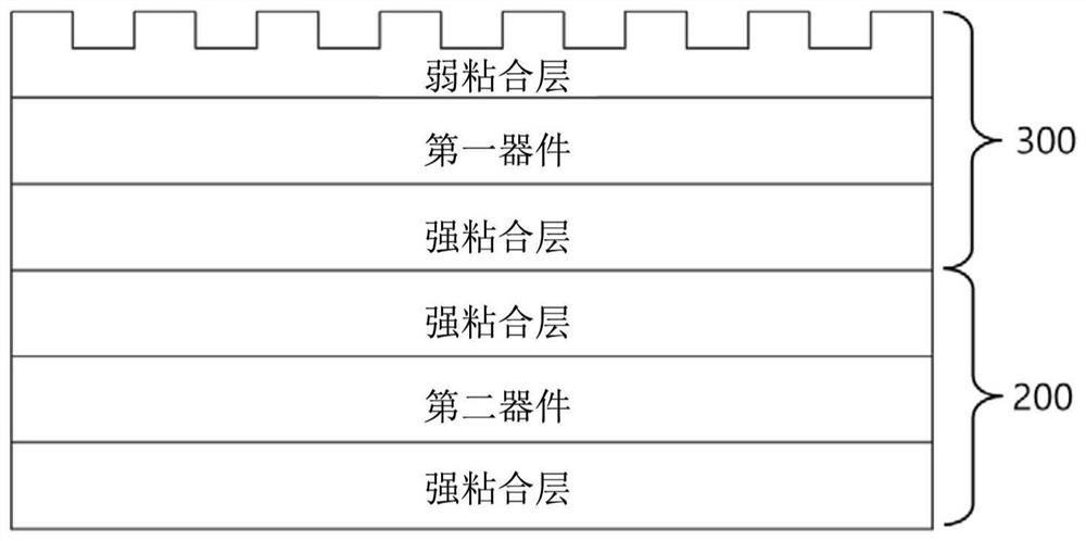
[0122] figure 2 It is a sectional view showing the structure of the bonded chuck member in which the upper surface has a patterned structure according to the present invention.

[0123] The adhesive chuck member of the present invention is formed by bonding the patterned adhesive layer 300 to the strong adhesive sheet 200 .

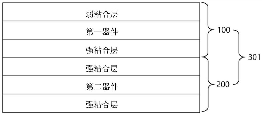
[0124] In the patterned adhesive layer 300, a strong adhesive layer is formed under the first device and a weak adhesive layer is formed above the first device. Unlike the prior art, the weak adhesive layer is patterned to have a concavo-convex structure. The strong adhesive layer of the first device is bonded to the strong adhesive sheet 200, which is a sheet with strong adhesive layers formed on both the upper and lower sides of the second device.

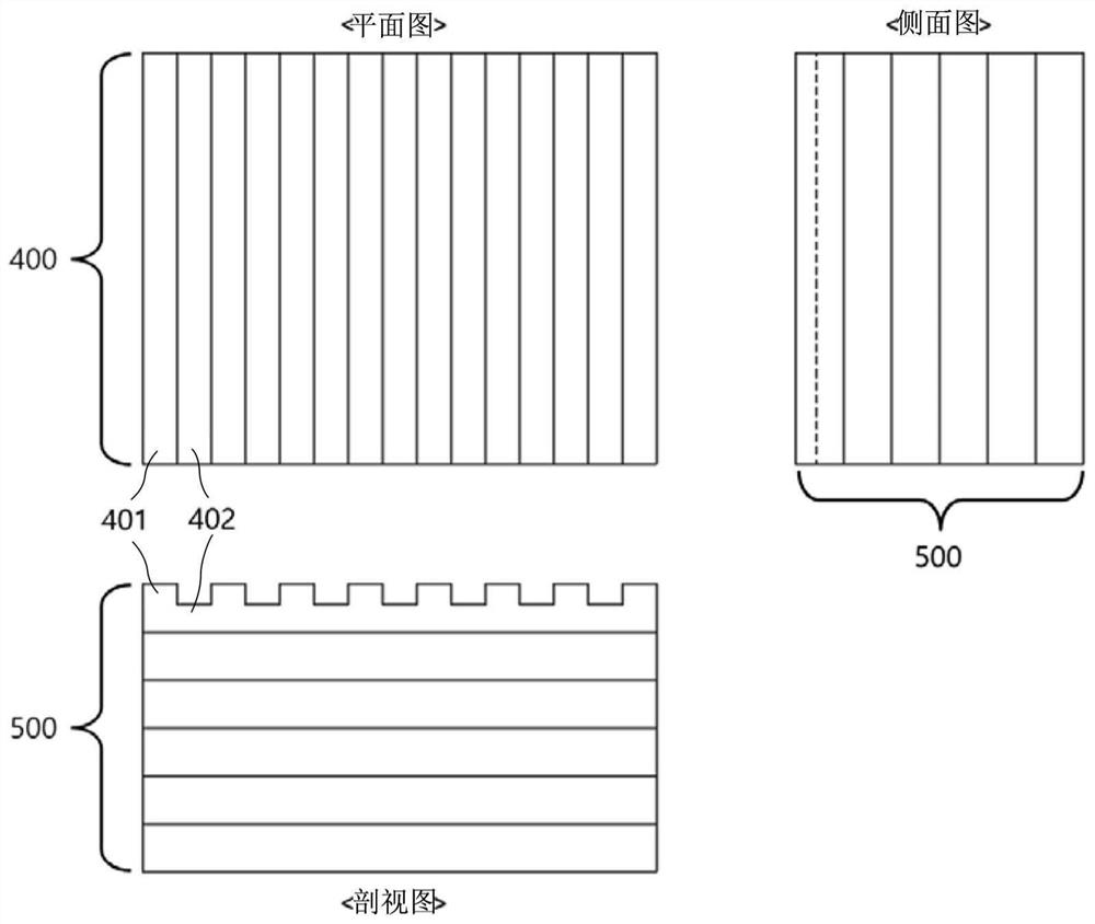
[0125] image 3 is a stripe-shaped adhesive chuck member 500 showing the ...


PUM

PropertyMeasurementUnit
Thicknessaaaaaaaaaa

Abstract

The present invention relates to an adhesive chuck member, a pattern forming method thereof, and a substrate chucking method and system. The adhesive chuck member uses an adhesive for supporting and fixing a large-area substrate in a manufacturing process of a display, a semiconductor, or the like, and a large-area bonding chuck which applies a conventional non-patterned general bonding layer applies a patterned bonding layer or an adhesive of a bonding layer having a structure of any form, thereby reducing or eliminating the phenomenon that the adhesive layer is peeled off and transferred tothe substrate when the releasing chucking of the detachment substrate is executed while performing the conventional function of supporting and fixing a conventional large-area substrate in the same manner. When the chucking of an adhesive substrate and the releasing chucking of the detachment substrate are performed, the substrate stress is reduced, thereby preventing the substrate from being damaged. The area of the adhesive layer adhered to the substrate is reduced so as to be relatively reduced, so that the area of the substrate surface that becomes hydrophobic is reduced, thereby providinga reduction in defects and stability of a process applied to the portion.

Description

technical field [0001] The present invention relates to an invention related to a chuck for supporting, fixing and handling substrates in processes such as displays, semiconductors, etc., and in particular, relates to a solution for reducing or removing weak adhesive layers when dismounting substrates (unchucking) The phenomenon of being peeled or transferred by the substrate, or when chucking or de-chucking, reduces the stress on the substrate and reduces the damage factors, which can effectively improve mass production. Background technique [0002] In the display industry, the general function of the chuck is used for the purpose of supporting and fixing the panel substrate inside the vacuum equipment, and the chuck is used when actually mass-producing the manufacturing process. The substrate supporting carrier includes a chuck or a table, among which chucks are classified according to various types of chucking mechanisms such as adhesive chucks, magnet chucks, and electr...

Claims


Application Information

Patent Timeline
IPC IPC(8): B65D6/04B65D25/10B65D65/40
CPCB65D9/00B65D25/10B65D65/40Y02P40/57H01L21/683H01L21/68785H01L24/28H01L21/306H01L2221/6835
Inventor 李相旻徐庭国金英俊尹景煜
Owner YAS
Learn More